Synchronizing Item Numbers Across Multiple Cut Lists or BOMs
I was recently presented with an interesting request from someone on a SOLIDWORKS support case. They had designed a weldment model and wanted to break it up into several subgroups to highlight specific regions, so they created additional part files by selecting groups of bodies and using the Insert Into New Part tool. A problem then arose when they created drawings for their models: The cut list item numbers in the groups didn’t match those in the top-level model. Since the groups were separate files, each cut list was unique to the particular model with which it was associated; the numbering scheme would start over at 1 every time. To make it easier for someone reading the drawings to figure out where every member is used, this user wanted each item to have the same number in all cut lists that reference it, but how can this be done?
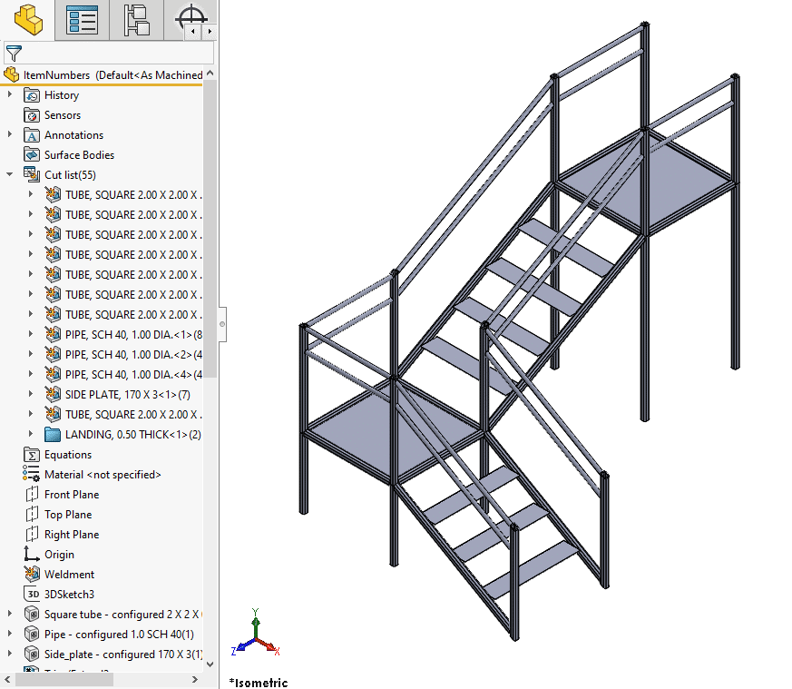
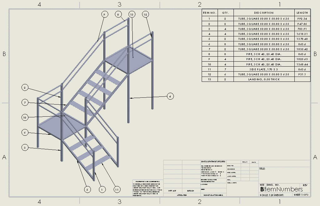
From what I have found, there are two ways to approach this issue. One option allows you to store everything in a single file, using display states or the Select Bodies tool to define the different subgroups. The other option involves splitting the model into different files for each group, creating a new numbering system as a custom property and adding that property to the cut lists in the separate drawings. I will discuss the successes and limitations of both methods using the weldment model shown below. Although I will only focus on cut lists, the same procedures can be applied to BOMs.
Method 1A: Display States
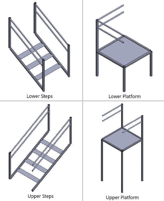
Let’s say I want four subgroups for the model: the lower set of steps, the lower platform, the upper set of steps, and the upper platform. Additionally, for this first scenario, let’s say I do not want to create separate models for these groups. One way to define my groups then is with display states.
If you are not familiar with display states, you can think of them as a less-powerful alternative to configurations. Whereas configurations allow you to vary a wide array of parameters (e.g., feature suppression states, dimension values, part materials), display states are limited to modifying visual properties. These visual properties include appearance, transparency, display style, and visibility. Display states don’t create separate copies of a model like configurations do, so they tend to contribute less to the overall file size than configurations. While display states are most commonly used in assemblies, they are also well-suited for multibody parts like weldments.
(If you are interested in learning about more characteristics of display states, I’d recommend taking a look at this article.)
I will create each of my four new display states by selecting all of the bodies I want to constitute a particular group (turning on the Solid Bodies selection filter helps here), right-clicking and selecting Isolate, and hitting the Save icon from the Isolate window to create a display state from that selection. (This is not the only way to create display states, but it is the easiest for this application.) In addition to these four display states, I still have the Default display state, which shows the full model.
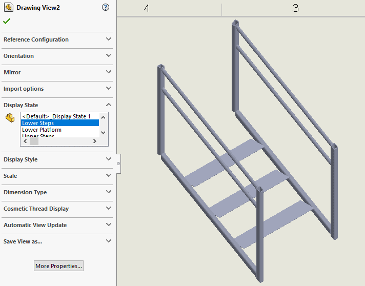
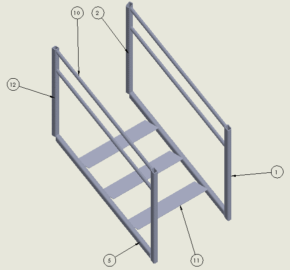
Now that I have my display states defined, I can move on to the drawing. The first sheet will have an isometric view of the overall model, ballooned based on an accompanying cut list. Each following sheet will be of a different display state. For these later sheets, I insert a view of the full model again, and then in the view’s PropertyManager there is a section that lets me choose which display state to use.
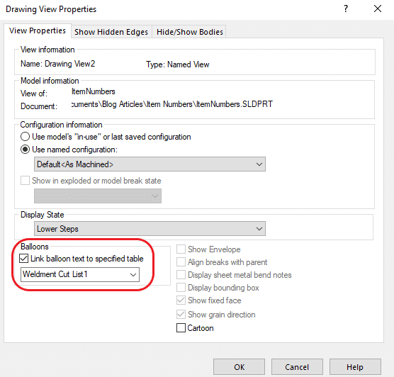
To ensure the balloons on the subgroup views are synchronized with the numbers on the overall cut list from the first sheet, I can right-click a subgroup drawing view, open Properties, turn on the checkbox for “Link balloon text to specified table,” and select the table I created on Sheet1. This guarantees that any balloons I add to the drawing view will use the item numbers given on the original cut list. (In my model, the balloons are fine whether I do this or not. This option is used if you are ballooning a different configuration than the one tied to the cut list/BOM, so if you aren’t changing configurations at any point you shouldn’t need to worry about it. Still, I recommend checking it just to be safe.)
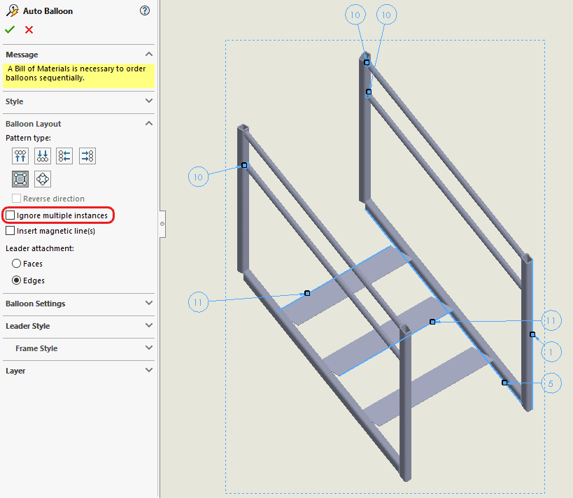
There are two main issues with this method. The first relates to the Auto Balloon tool. By default, Auto Balloon only adds balloons to items that have not been called out elsewhere; if there are already balloons for certain items in another view, Auto Balloon will skip those items in the current view. However, if you turn off the “Ignore multiple instances” checkbox in the Auto Balloon PropertyManager, it will add balloons regardless of whether they already exist in other views. The problem is that it will add balloons for multiple instances of the same item, and it does not seem to capture all of the items in the view, so you will likely have to delete redundant callouts and add in missing ones manually with the Balloon tool. In the picture below, I have turned off “Ignore multiple instances.” You can see that it labels items 10 and 11 multiple times, and it fails to call out items 2 and 12.
The second issue is related to the view itself. When working in a drawing view, you can only select entities that are present in the part’s current display state. So, if your part file has one of the subgroup display states active, then in your drawing views you will be unable to select any faces or edges on bodies that are hidden in that display state. This is a known issue reported a couple times in the SOLIDWORKS Knowledge Base (e.g., SPRs #1111940 and #1113538). Until it is fixed, your best options will be to either toggle the display state at the part level to whichever subgroup you want to work on in the drawing; or you can keep the part in a display state that shows the full model, in which case all edges and faces in the part will be selectable.
Method 1B: Select Bodies
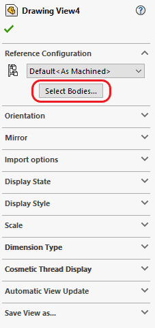
A simpler alternative to display states is the Select Bodies tool, accessible in the PropertyManager for a drawing view. This gives you the ability to choose what bodies should be considered for the view, letting you define groups similar to what I described for display states. It will hide all other bodies in the model and fit the view’s bounding box based on what remains. This method gives you a workaround to the selection issues mentioned above. If you use Select Bodies, you will be able to select any entities on those bodies in your drawing view, even if they are not visible in the part’s active display state.
Select Bodies is limited, relative to display states, in a couple ways. The capabilities are less extensive—Select Bodies only permits hiding and showing components in different drawing views. The selections you make do not propagate back to the original part file, nor are the groups stored anywhere within the drawing, whereas display states exist and can be activated wherever that model is used. Still, if you only care about the groups for the sake of the drawings, and if you want to avoid the edge selection difficulties that come with display states, then Select Bodies can be a useful alternative.
Method 2: Custom Properties
If you do want to split up your model into separate files for each subgroup, then the custom property route may be more appropriate. You can create a custom property for a new item-numbering system in the top-level model and have it propagate to all of the lower-level parts. Rather than using the standard Item Number property in your subgroups’ cut lists, they can instead reference this new property.
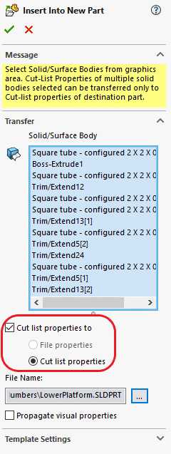
I will recreate my four subgroups as separate files using the Insert Into New Part tool. To make sure all of the properties transfer over properly, I can select “Cut list properties to” > “Cut list properties” in the Insert Into New Part PropertyManager.
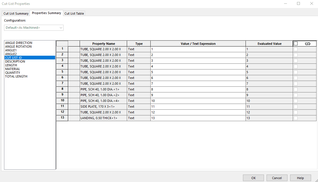
Back in the top-level model, I want a new custom property to be added to each item in the cut list. To do this, I will first right-click the Weldment feature in the FeatureManager and select Properties. In this dialog, I will name my property “Cut List ID,” set the Type to Text, and leave the Value/Text Expression field blank. Now that this is defined, I need to assign a different value for every cut list item. I can right-click any of the items from my Cut List folder in the FeatureManager and select Properties to open the Cut-List Properties dialog. In the Properties Summary tab, I can see the value given to each cut list item for a particular property. After selecting my Cut List ID property from the list on the left, I will go down the Value/Text Expression column assigning each item a number.
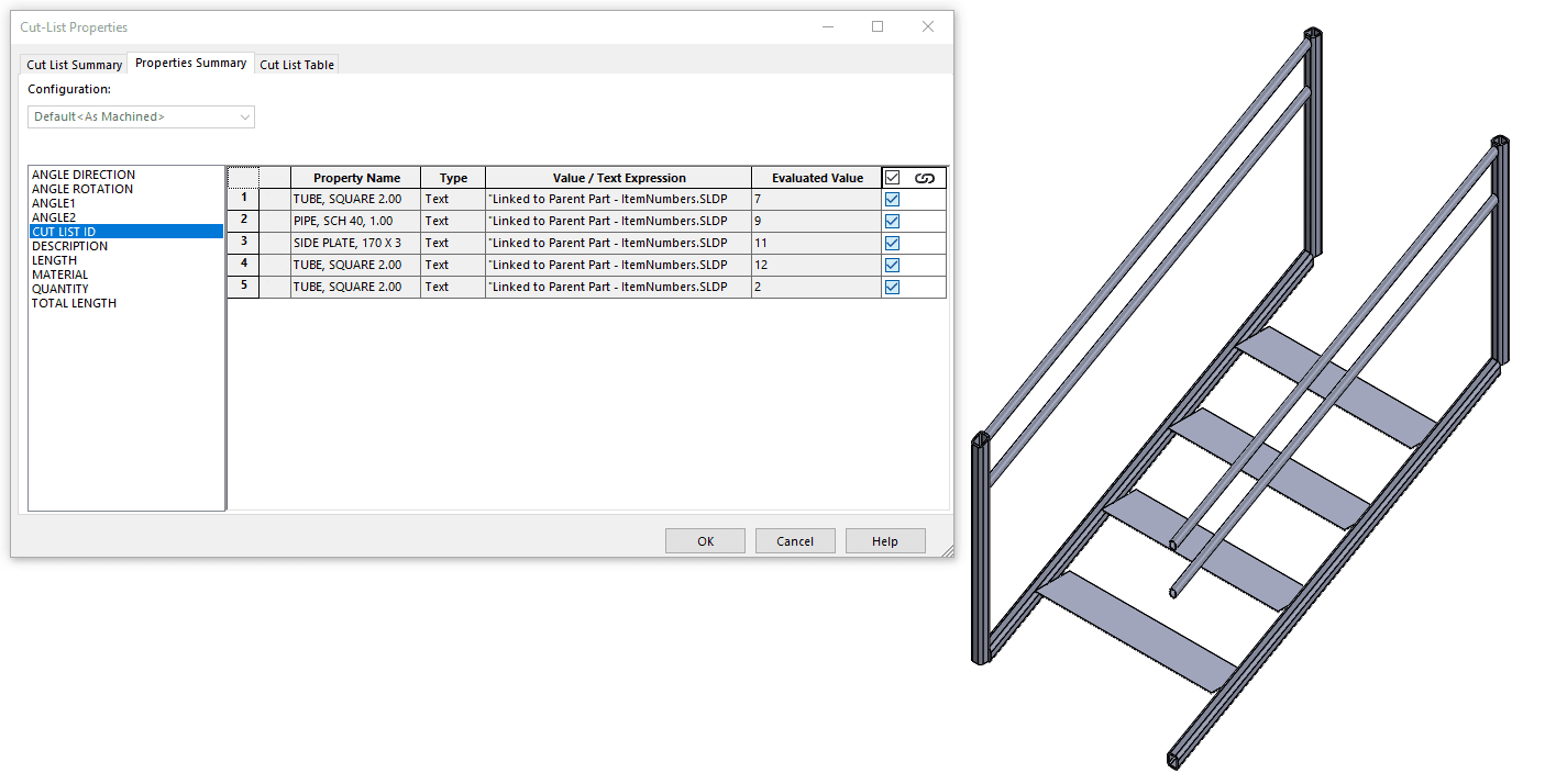
I can open one of the subgroup parts to see that the properties have transferred. Notice that the Value/Text Expression for each item in this part is tied to the parent model. This is important to recognize. If you change a property value in the top-level model (or make any change to the top-level model, for that matter), the derived part will not update automatically. In order for it to update, it must be open while that parent file is also open so the external references can be in context. At that point, you can save the derived model and it will retain the changes.
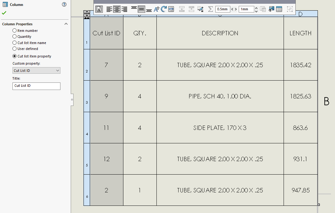
Now that I have these custom properties defined, I will open a drawing for each subgroup and insert a cut list. The template I am using for my cut lists has four columns: Item Number, Quantity, Description, and Length. I’ll leave the final three as they are, but I will edit the Item Number column. If I click on the column header, it selects all cells in that column and opens the Column PropertyManager. From that PropertyManager, I can change the Column Properties from Item Number to Cut List Item Property and select Cut List ID from the Custom Property dropdown menu. (If you are doing this in a BOM, you will need to click the column header and then the Column Property button from the toolbar that pops up. This will let you change the property being used for the column.)
This cut list can now be cross-referenced with those of the top-level model and the other groups to identify members of the same family. To clean things up, I will right-click somewhere in my Cut List ID column and select Sort > Ascending to reorder the cut list rows according to the ID number. If I wanted to make a new cut list template (so I wouldn’t have to redefine the front column every time), I could right-click a cell in the table, choose Save As, and drop it into my usual template folder.
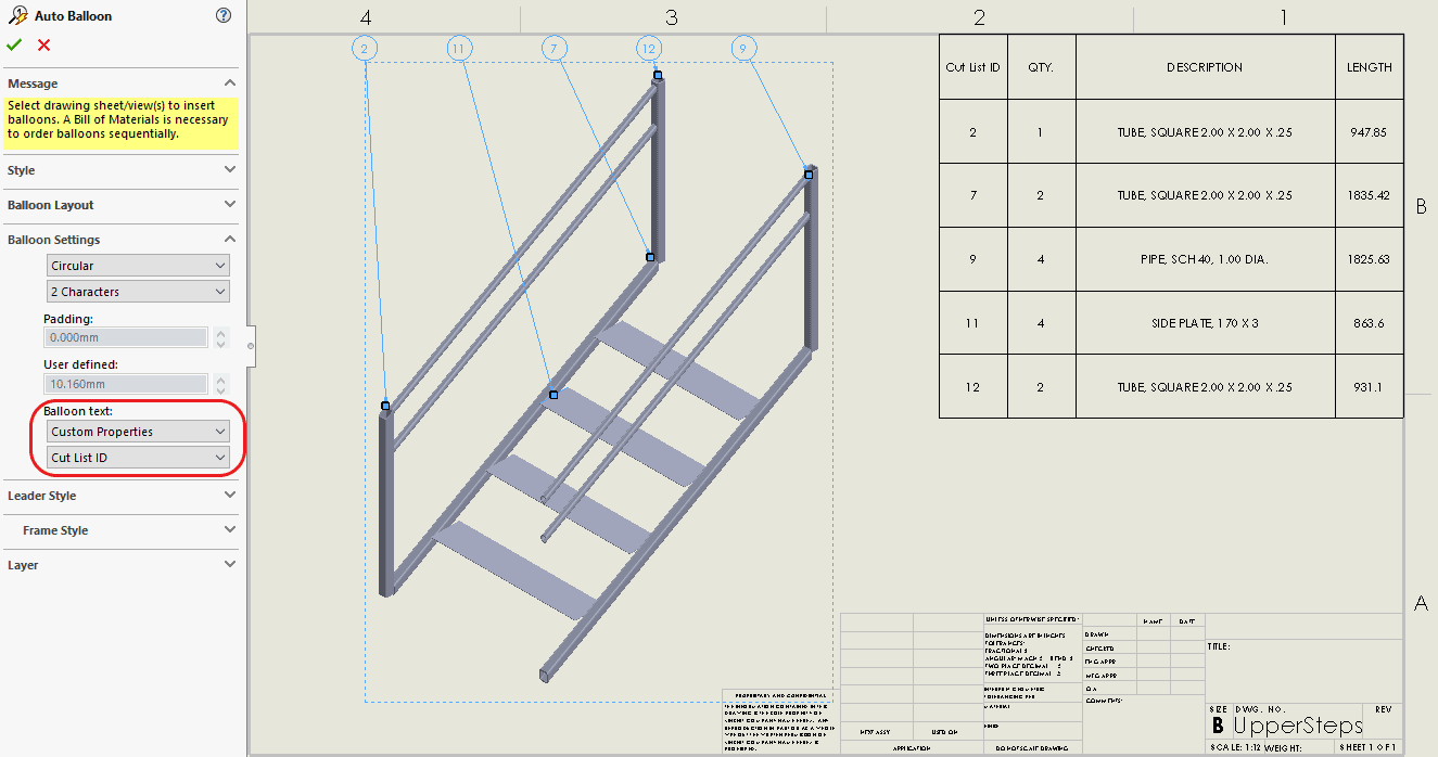
But what about the balloons? At this point, if I were to add balloons, they would not reference the correct values; they are still programmed to take the Item Number for each component. I can use the Auto Balloon tool here, but I need to make a change in the PropertyManager to set it up correctly. In the Balloon Settings category, I will change the Balloon Text from Item Number to Custom Properties and select Cut List ID from the second dropdown list. Now my balloons match the values shown in the Cut List ID column.
Overall, this method has some benefits over the single-file options. Since each group has its own drawing file, you will not run into the Auto Balloon inconsistencies I mentioned before. Additionally, this route avoids the problems with edge/face selection associated with display states. This may not be the best option for large models though. You could end up needing many extra files depending on how many subgroups are required for your project, so there are some potential file management concerns. Furthermore, since you are creating external references, it may be tedious to open each subgroup part to rebuild when changes are made to the top-level model. So, there are still some scenarios where the single-file approach may be more appropriate, but you can determine which makes the most sense to you as you play around with your options.
I hope this gave you some ideas of how you can tailor your cut lists to your projects’ needs. If you have any questions about these processes or similar issues, feel free to reach out to our Technical Support team for assistance.
Anthony Sandri, CSWE
Application Engineer
Computer Aided Technology, Inc.