Tackling the LARGE DISPLACEMENT Error Message
What does one do when he/she sees the error message shown in the picture:
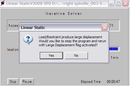
This error message is probably one of the most common ones that a COSMOS user encounters in analysis. The first reaction that one gets is that this is impossible. You know for a fact that the load cannot possibly cause large deflections. Statistically speaking, the confidence levels on FEA drops drastically at this point, and I would not blame you for it right now (later, maybe)!!
So, how does one negotiate this message? You have a simple decision to make at this point:
- Hit YES, and it will say that the analysis failed, and it requires you to activate the large displacement flag (this flag is used if you know that the geometry is undergoing large displacement, and you want to solve this is a geometrically non-linear problem). However, that is against your gut feeling since you know this load cannot cause large displacements!
- Hit NO, and it will seemingly complete the calculation and give you Result Plots (inaccurate since the solver came up with an error message in the process of the calculation).
Since this message can pop up either at the part or the assembly level, let us investigate them one at a time. For both cases, make sure you select NO at the error message window before proceeding.
PART LEVEL
There are three possible causes for this at the part level.
- Your load is way too high – probably an oversight when defining the force/pressure condition in terms of either number of 0’s, or the units.
- The material properties are incorrect – inconsistent units or the values of the material properties while custom defining materials.
- Insufficient/negligible restraints – The location of the restraint was way too small to support the entire load, and/or the part is swiveling about one of the axes at the restraint location (as if it were hinged at that location).
SOLUTION – Check the values indicated in the first two cases above as a first step. If they look correct, then take a look at an animation of the displacement plot (set the deformation scale to automatic). The animation will tell you as to what direction(s) are still unaccounted for. If the directions of restraint are accurate, then examine the location, and see if it is on an edge or a small face. Make sure that the restraints are on the right areas.
ASSEMBLY LEVEL
SOLUTION – The problem at the assembly level is a superset of the part level issue. Thus, the first steps would be to try out the fixes recommended in the above section for each part in the assembly, and each restraint/load defined in the property manager.
If those do not fix the issue, then there exists only one possible cause – one or more of the components in the assembly is not sufficiently restrained. In other words, there are components that are freely positioned in the assembly, and the moment the solver tries to apply the load to the structure, these components freely float away in one of the unrestrained directions. This can be verified either by animating the displacement plot and looking at which components fly off in space.
Will mating them correctly in SOLIDWORKS help?
The answer is negative. Mates in SOLIDWORKS are a way of dictating the initial position of the components, and they do not carry over into COSMOS.
Hence, the resolution is to either add restraints to the un-constrained components, or to bond them using local contact sets to the adjoining components that carry sufficient restraints. Either of these methods will sufficiently constrain the free component.
These above methods should sufficiently address the large displacement flag. This flag is very easy to tackle since it is completely dependent on what you defined in the pre-processing steps. Keep in mind that a good analysis is one where you do not encounter any error messages, and the animation of the displacement plot is consistent with what intuitively makes sense. If FEA is garbage in garbage out, then re-cycling garbage has to give you a good usable solution!! So keep at it in terms of trying to troubleshoot your analysis studies.