Understanding SOLIDWORKS Assembly FeatureManager Design Tree
The FeatureManager Design Tree is the list of instructions that tells SOLIDWORKS how to build your Parts and Assemblies. In Parts, the FeatureManager includes all the features that make up your part and are history-based and order-dependent. The FeatureManager Design Tree in Assemblies includes the following items:
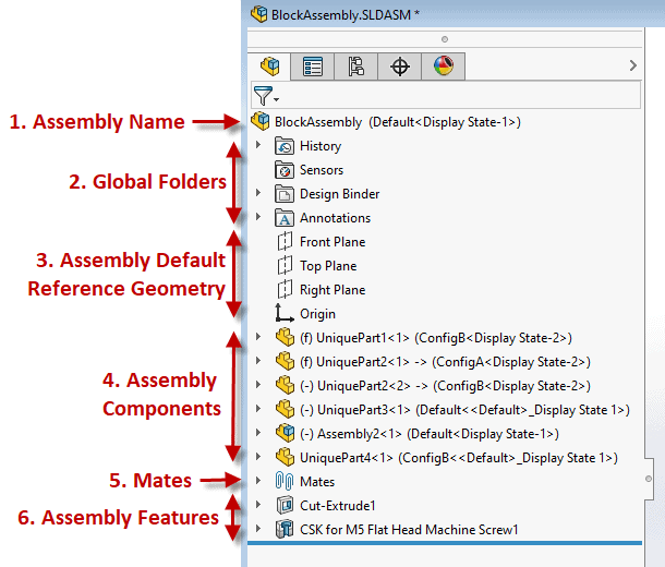
This blog is going to focus on the Assembly Components section. You can see from the screenshot above that Assembly Components in the FeatureManager Design Tree include other fluff besides just the part or subassembly name.
Zooming in on the Assembly Components section, the first thing we see next to each part or component name is the part or assembly icon showing whether that assembly component is a part or subassembly of the top-level assembly.
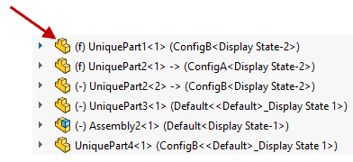
Next, we see either (f), (-), or neither next to the part or assembly icon. These letters tell us about the ability of the component to move in the top-level assembly.
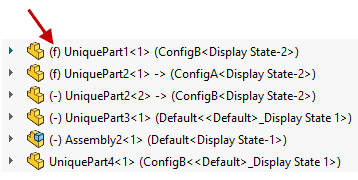
By default, the first part inserted into the assembly is Fixed, which is depicted by (f). That tells us the part cannot translate or rotate about any axis simply because we said so. You can also Fix a part by clicking the green checkmark when inserting components which will fix the origin of the part to the origin of the top-level assembly.
The minus sign (-) shows up next to any component that has at least one degree of freedom (translate or rotate about at least ONE of the x, y, or z axes). This is also known as “Float”. You can change a Fixed component to a Float component by right-clicking a component from the Design Tree and choosing “Float” and vice versa to change from Float to Fix by choosing “Fix”.
Neither the (f) or the (-) show up next to an assembly component when we have removed ALL degrees of freedom by adding Mates.
The Part or Subassembly File Name is the next thing we see.
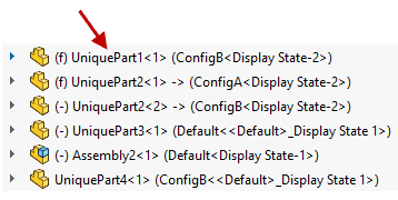
Following the File Name is a number (<1>, <2>, etc). This number is the Instance Count of each unique part or subassembly that exists in this assembly. It is also important to note that this instance count continues even if parts and subassemblies have been deleted, so the highest instance number here may not always equal the quantity of that part or subassembly in the top-level assembly.
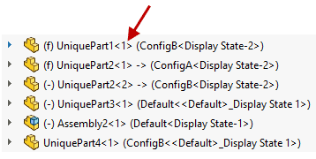
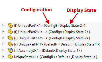
Finally, we have the Configuration Name, followed by the Display State.
Hopefully, this gives you a better understanding of your Assembly FeatureManager Design Tree!
Nicole Kelley
Support Engineer
Computer Aided Technology, LLC