Using Alternate Symbols in SOLIDWORKS Electrical
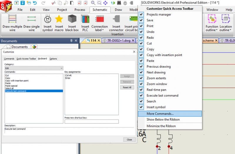
Laying out symbols and wire connections is a snap with SOLIDWORKS Schematic. There are several ways you can get repeating steps set up for speed in your drawing. One of my tricks is to go to the old standby being “Execute last command”. I have set up 2 keystroke combinations that allow me to quickly redo the last function I had selected.
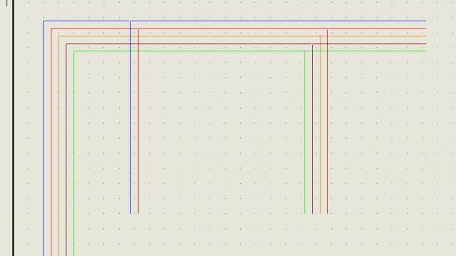
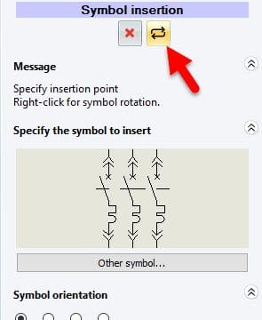
When laying out my wire styles, it is a snap to lay out several paths. Adding symbols can be done in the same way, using the last command short cut. Also available would be if the same symbol is desired, the pin command. Pin repeats the symbols based on the dialog selections used.
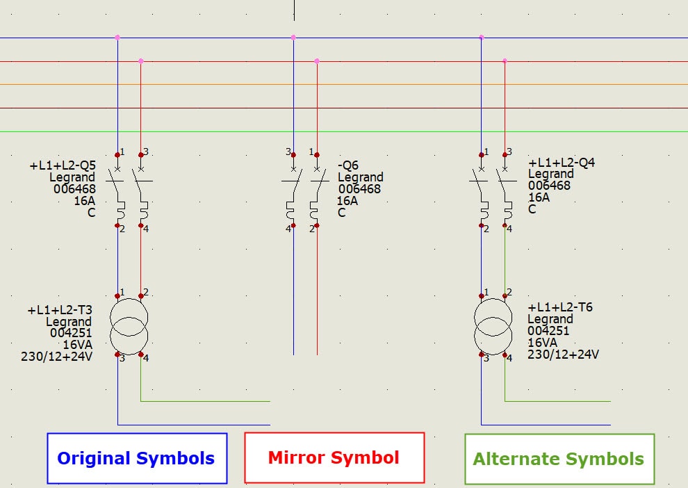
One problem that may occur on a drawing then is the information surrounding a symbol may become a bit crowded. Another instance would be information attributes may appear too near a wire style for some. To fix this error some like to point the mirror function in the symbol. That is not the best solution for this issue and also causes terminals to invert, which may be a disaster. What I have shown users in the past is to create an additional symbol, with the attribute information moved or mirrored to the other side of the original symbol. Using this additional symbol idea, users can create several versions of symbols that will best display or suit their design needs. Having these alternate symbols allows users to swap them out with speed instead of moving attributes.
Corey Kubichka
CATI Electrical Product Manager
Computer Aided Technology, Inc.