SOLIDWORKS: Weldments – Creating Curved and Nonstandard Miters
Weldments – Creating Curved and Nonstandard Miters
Using SOLIDWORKS Weldments is a huge time saver when it comes to creating welded structures, frames, and structural members, but if you’ve used Weldments long enough, you’ve probably found out that the End Miter Corner Treatment only applies a 45-degree miter.
This is great for right angled beams using the same Weldment Profile but not so great for multiple profiles of different sizes and nonstandard edge angles.
Let’s look at the following example:
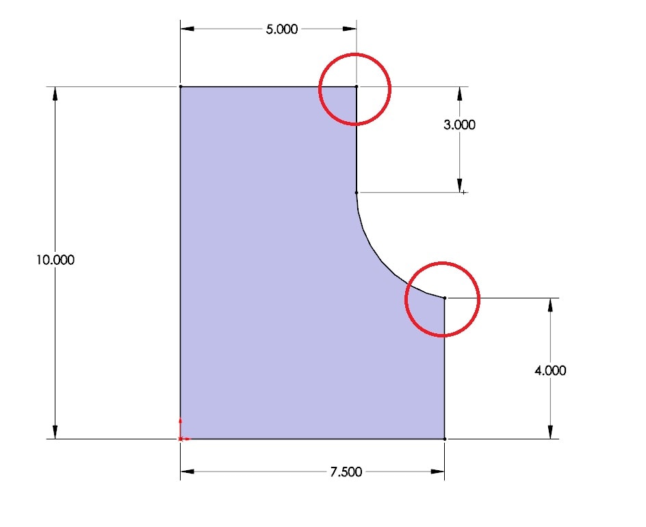
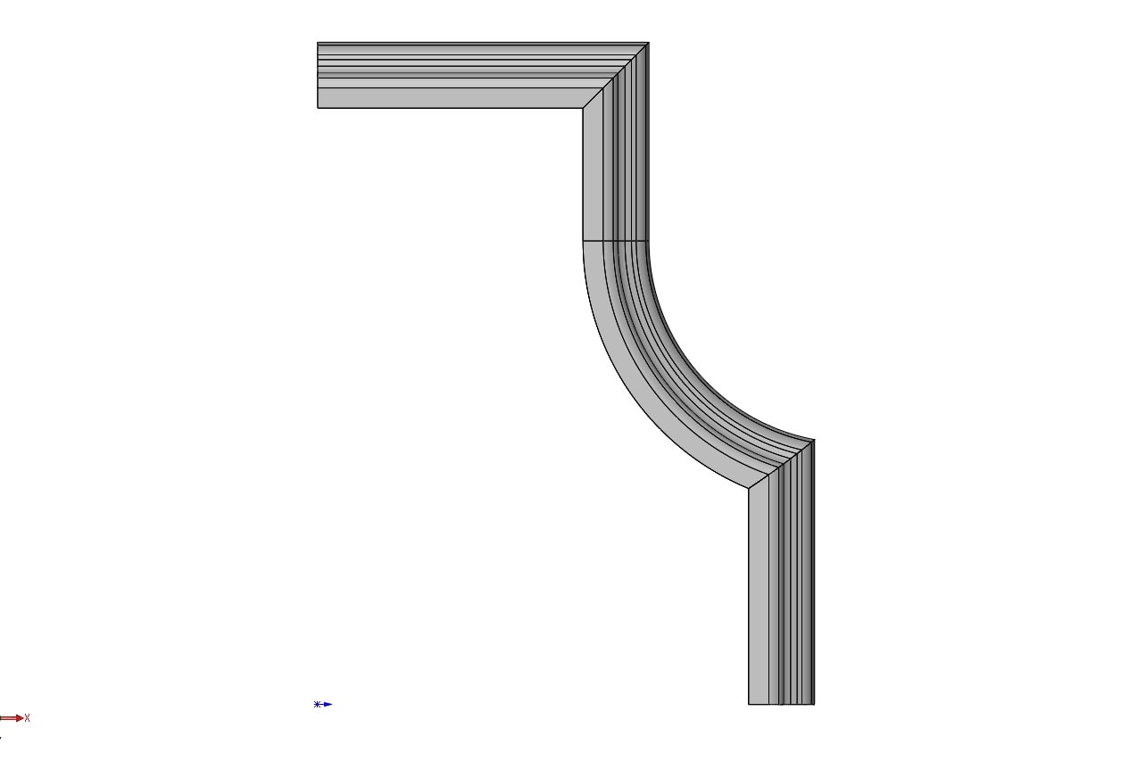
This will be our Weldment Path. Take note of the two circled edges. One is a standard 90-degree angle while the other is a nonstandard edge where a curve meets a line.
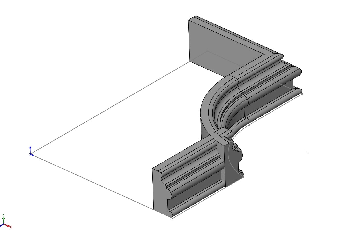
Let’s apply the Weldment Profile:
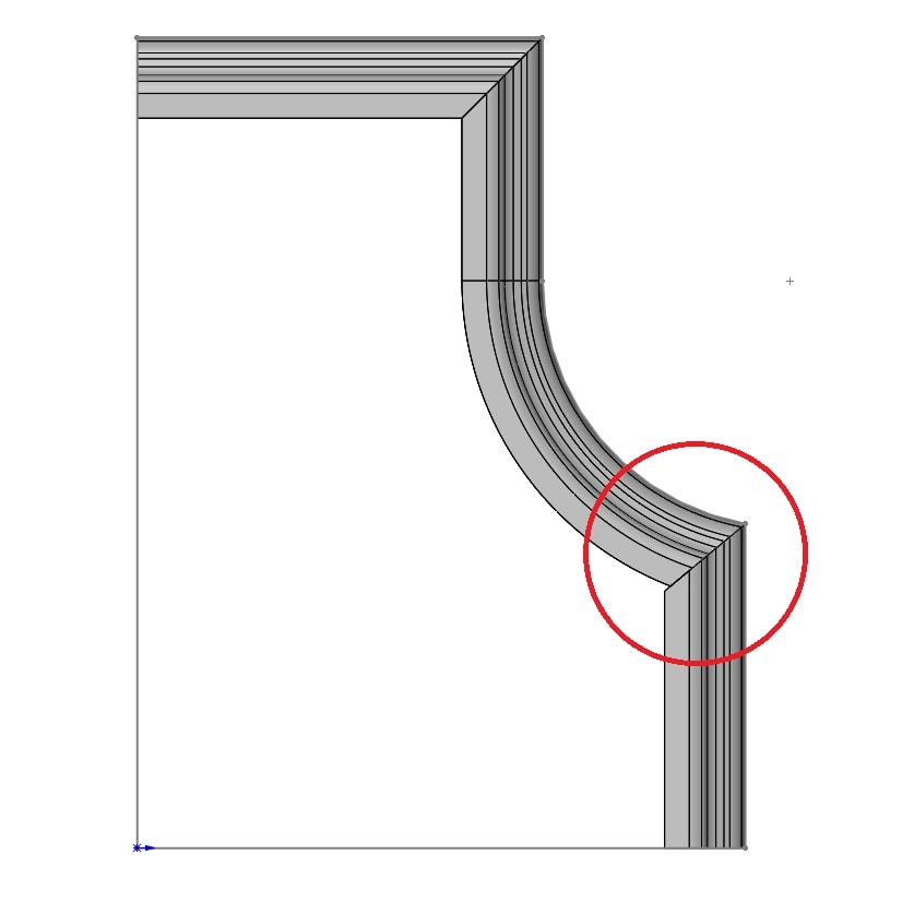
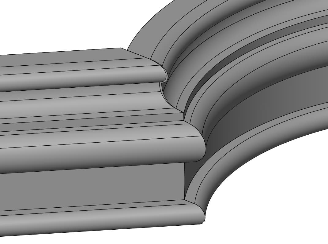
Notice the profile doesn’t quite meet up as it should. Here’s another view to show the standard 45-degree miter won’t work.
To solve this issue, I will use a combination of Surfacing techniques and a Weldment command called ‘Trim/Extend’.
To begin, I will create a New Group within my Weldment and separate out the two paths at the nonstandard edge intersection as shown.
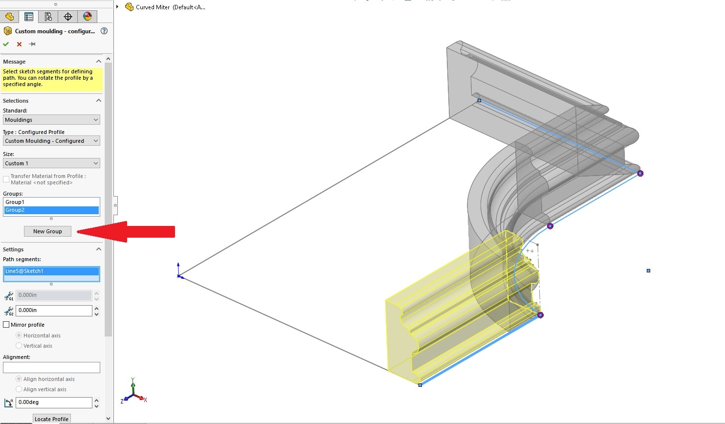
This will cause the two Groups to intersect.
The next step will be to define the correct intersection plane where the two Groups will meet. I will use the command Intersection Curve found in Tools > Sketch Tools > Intersection Curve and choose the two back faces of my Weldment as shown.
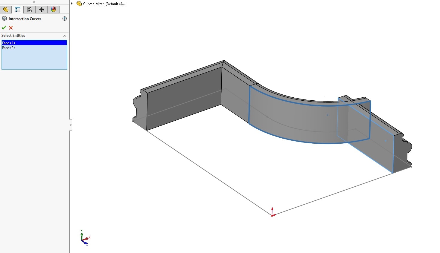
This will create a 3D Sketch line where our Weldment Groups meet. We can use this to determine the appropriate orientation of our Miter angle. Open a new sketch looking down on our weldment, and draw a line that represents the angle we need our Weldments to meet at.
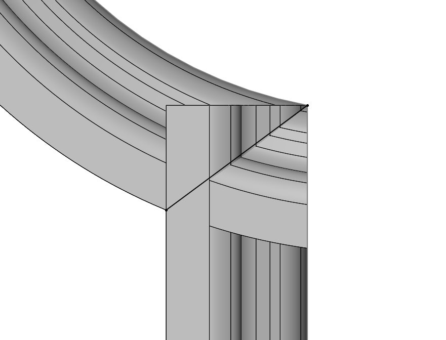
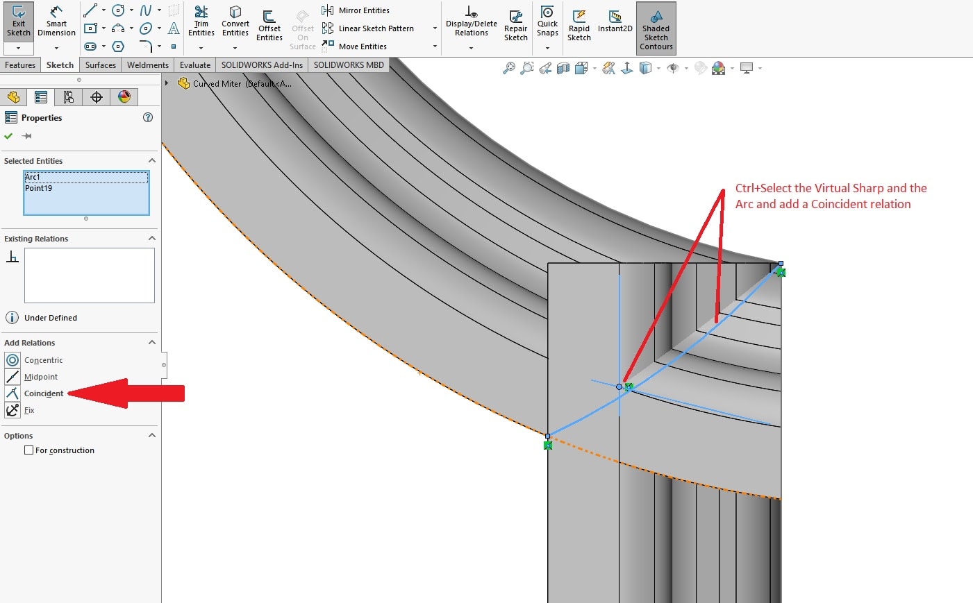
With the above case, we can visually see that a straight line does not intersect both Weldment Profiles exactly. If this was a standard angle between two different sized profiles, you could continue to the Surface creation step; however, for this specific case, we will need to capture our Intersection angle as a curved arc. We need our arc to pass through the intersection lines on our Weldment, so to be able to Snap to our intersection lines, I am going to Ctrl+Select two like Weldment Lines and use the Point Sketch Command to create a Virtual Sharp as shown.
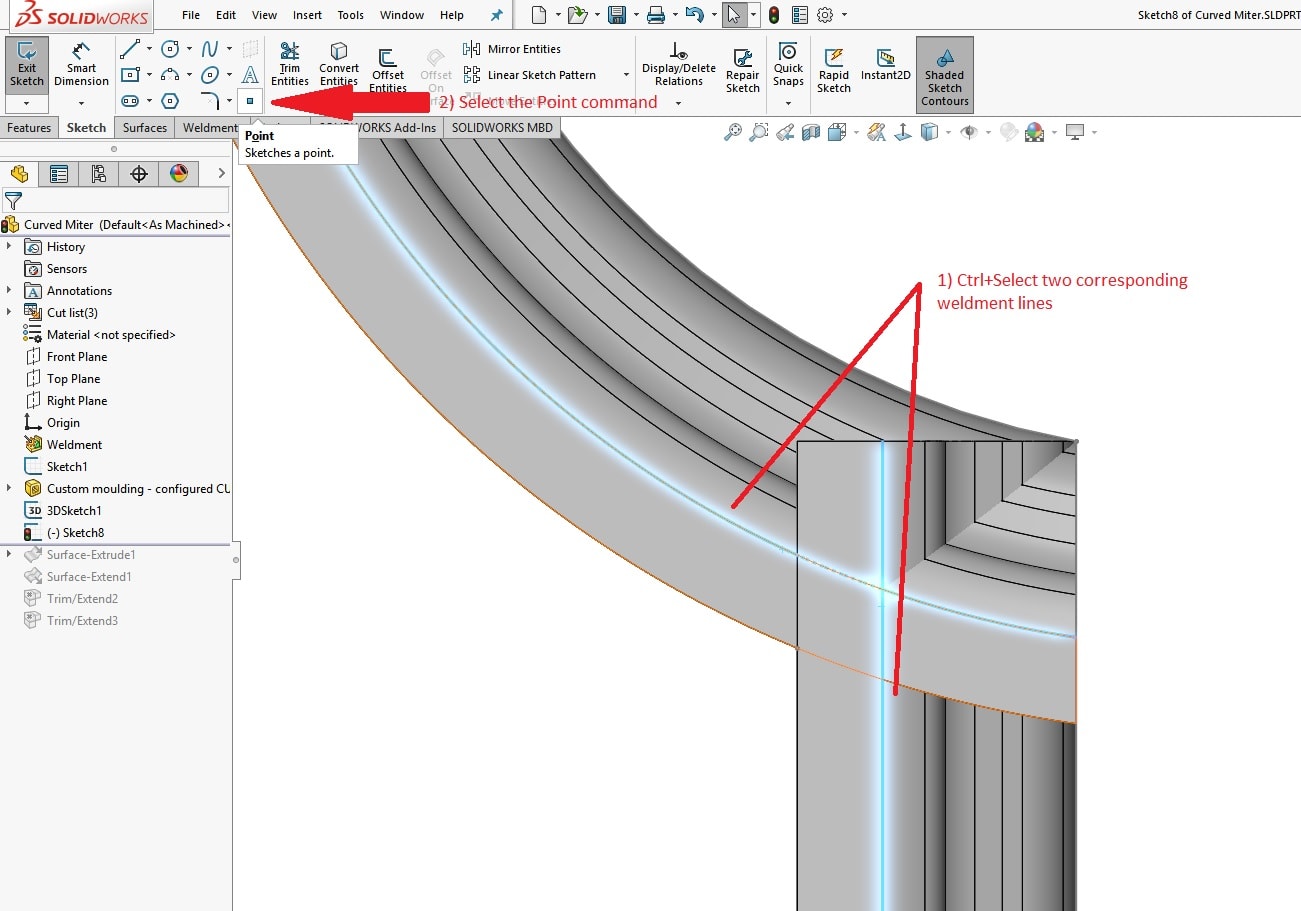
This will create a Virtual Sharp that we can then Snap our Sketch Arc to. Start by drawing an arc snapping to our Intersection line and our Edge point. Then Ctrl+Select the newly drawn arc and our Virtual Sharp and add a Coincident relation.
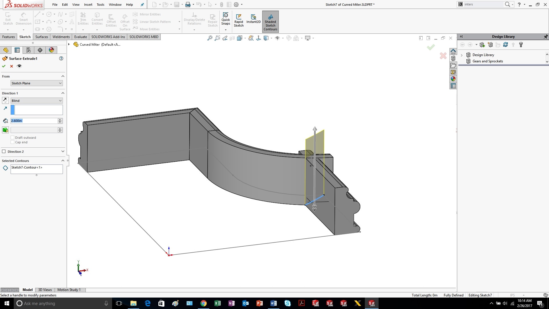
We can now create a Surface from our 2D arc using the command Extruded Surface found in Insert > Surface > Extruded Surface.
Make sure to visually confirm that your surface extends beyond all sides of your Weldment. If it does not, we can make our surface larger by using another Surfacing command called Extend Surface found in Insert > Surface > Extend Surface.
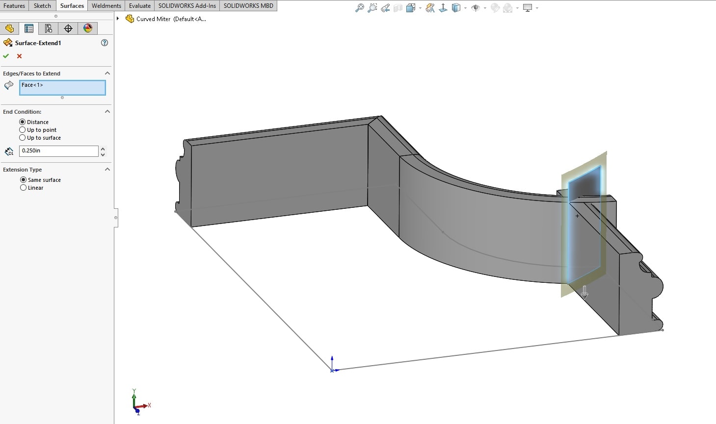
Select the surface face we just created and extend it, ensuring you have Distance and Same Surface selected. Visually check that your surface extends beyond each Weldment.
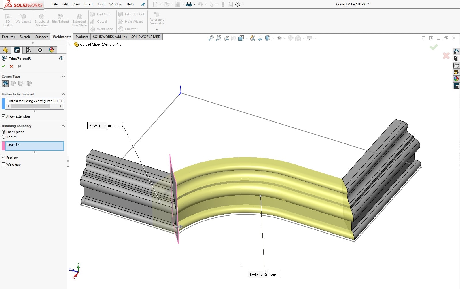
You can then use the Trim/Extend command found on the Weldments toolbar or Insert > Weldments > Trim/Extend. Select the Weldment body you want to trim and the surface body we created as the trim tool.
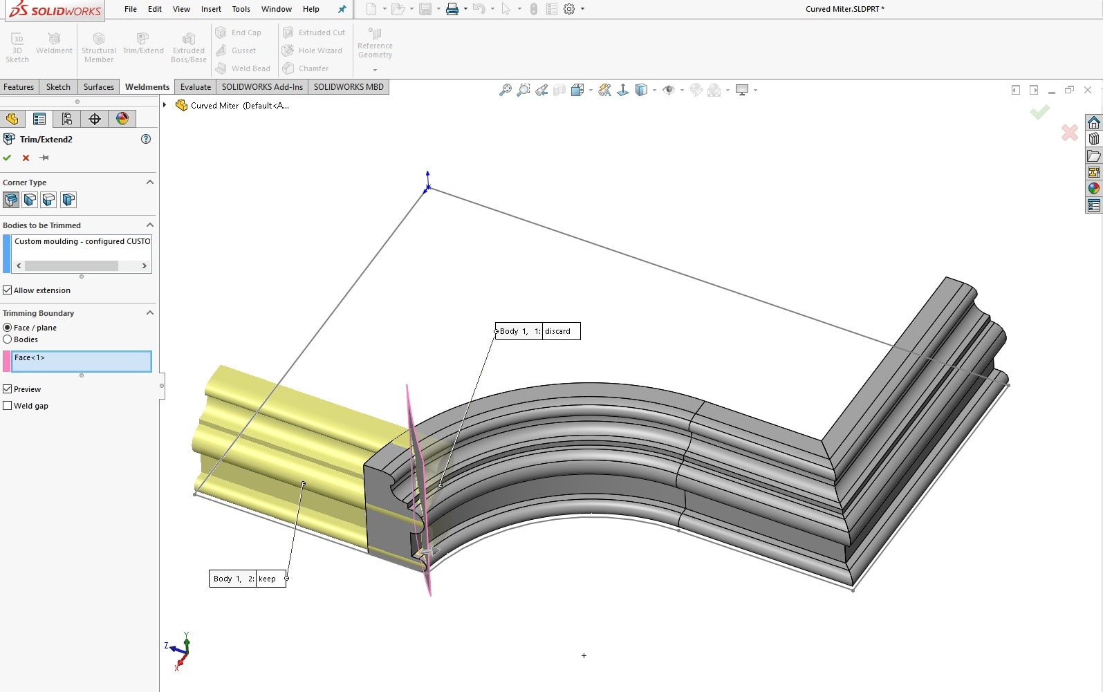
Repeat this step for the other Weldment body selecting the same surface as the trim tool. Make sure to have the correct Keep and Discard settings to only keep the Weldment bodies you need.
When finished, hide any sketches/surfaces you don’t need.
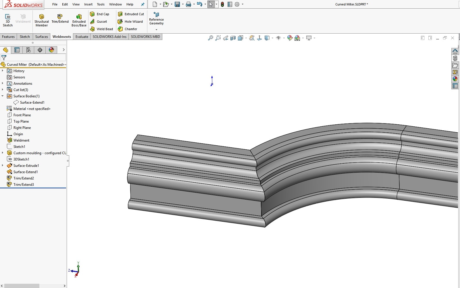
I hope this little Weldment trick in SOLIDWORKS helps you save some time and take your Weldment designs to the next level!
Jordan Puentes, CSWE
Application Engineer
Computer Aided Technology