When To Use A Bearing Load
The use of a bearing load is brought up frequently during training and technical support discussions. I want to elaborate on this topic with a simple example, illustrating when to use and when it is not necessary to use the bearing load.
Let’s step back a minute and talk about what a bearing load is. According to the SOLIDWORKS Help file:
Bearing Loads
Bearing loads develop between contacting cylindrical faces or edges of shells.
In most cases, the contacting faces or edges have the same radius. The bearing forces generate a non-uniform pressure at the interface of contact. You can select between a sinusoidal variation and a parabolic variation in the appropriate half-space, as shown in the figure.
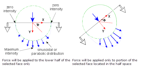
In contrast, a uniform load does not vary in strength closer to the tangency of the tube. The load is constant across the applied face.
Setup:
We will examine two models and four scenarios in this exercise. The models will be both a solid and a hollow shaft. The shaft dimensions will be 14″ long with a 2″ diameter. Additionally, the hollow shaft will have a wall thickness of 0.125″.
Both the Solid and Hollow tubes were loaded with a distributed and bearing load in order to compare and contrast the results. Both models were held fixed at either end. The load was applied to the entire length of the top half of the shaft in a vertical direction.

The Results:
Between the distributed and bearing load on the Solid model, there is no difference in stress and displacement. On the hollow tube, the bearing load shows a drastic difference in the displacement compared to the uniform load. The bearing load shows the majority of the load is being focused on the center of the tube.
Model Load Stress Displacement
| Model | Load | Stress | Displacement |
| Solid | 2000lb Distributed | 3943.6 psi | 0.001066 in. |
| Solid | 2000lb Bearing | 3943.4 psi | 0.001065 in |
| Hollow | 2000lb Distributed | 11,534.6 psi | 0.003009 in. |
| Hollow | 2000lb Bearing | 12,084.9 psi | 0.003467 in. |
Significant digits are for illustration only.
The stress is 4.5% higher in the ‘hollow shaft – bearing load’ combination as compared to the ‘hollow shaft – distributed load’ example.
Stress Above Displacement Below Solid Distributed Load
Stress Above Displacement Below Solid Bearing Load

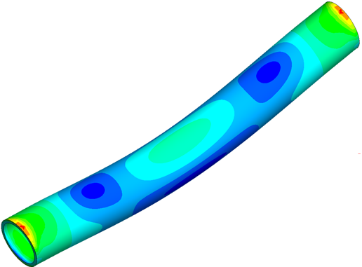
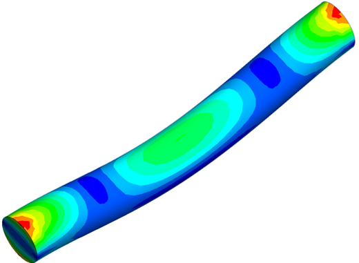
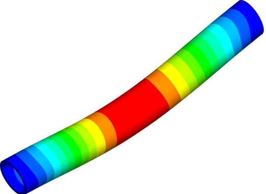
Stress Above Displacement Below Hollow Distributed Load
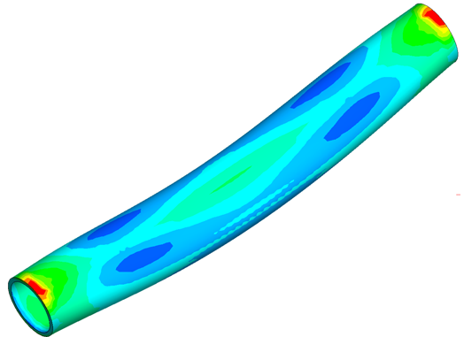
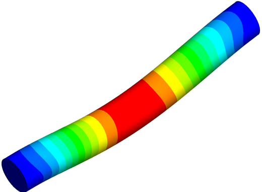
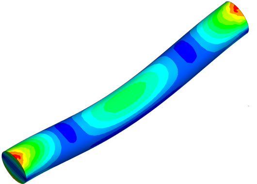
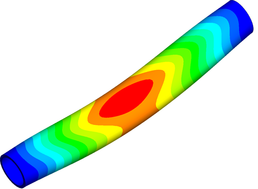
Stress Above Displacement Below Hollow Bearing Load
Summary:
In summary, the bearing load should be utilized when dealing with a hollow or thin walled, cylindrical geometry. Utilizing solid geometry the load differences do not affect the results. The solid geometry distributes the load throughout the solid volume and is inherently stiffer. The hollow tube, missing its internal mass, shows a difference in the displacement of the applied load. The uniform load displaced evenly from tangent edge to tangent edge where as the bearing load concentrated in the center.
A bearing load can be applied to solid and hollow cylindrical geometry however it is only necessary for hollow or thin geometry.