Work Smarter, Not Harder: Using Smart Components in SOLIDWORKS
With the constant push to get designs completed quickly, anything you can do to speed up your SOLIDWORKS modeling is an advantage. Smart Components are a lesser known tool that has been available in all versions of SOLIDWORKS for many years. If you are looking for some tricks to increase productivity, Smart Components should be on your list.
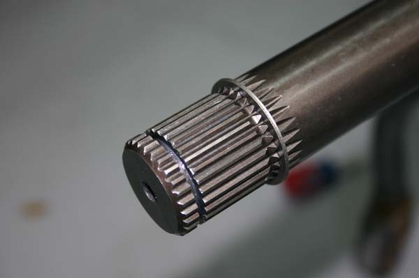
Everyone is familiar with setting up SOLIDWORKS part libraries to efficiently create new projects. A single file location for common parts can be very helpful in cases where designs share many of the same components. Frequently, these standard parts will require specific geometry to position them correctly in the assembly. A simple example would be an external snap ring. The snap ring will require a small revolved cut in a shaft to position it. Smart Components are a specific tool inside SOLIDWORKS that allow us to tie these library parts and these additional features together.
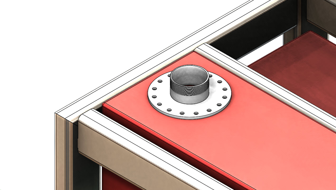
Turning library parts into Smart Components is a simple task. SOLIDWORKS makes it easy to attach additional components and even in-context features to these library parts. How do you take a library part and turn it into a Smart Component? For this example, let’s take this round fill plate used on fluid container designs.
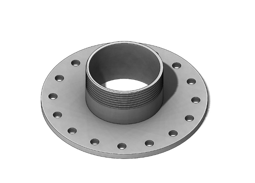
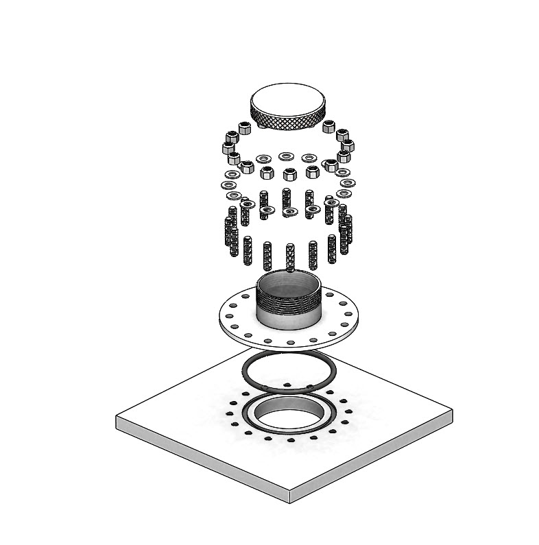
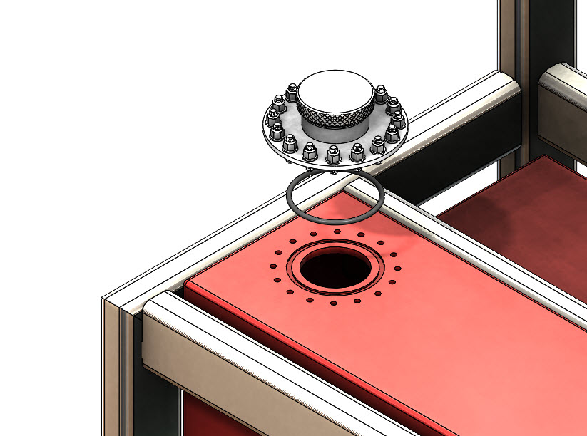
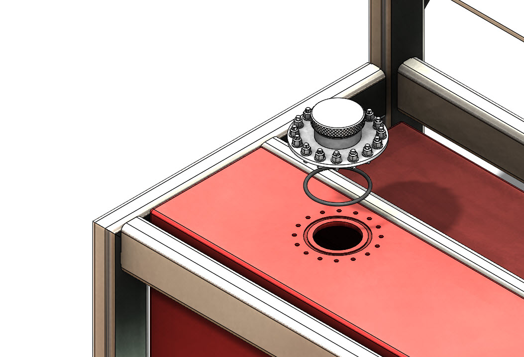
When used in projects, this fill plate will almost always require additional components and features. The needed components include a threaded cap, a rubber O-ring, threaded studs, washers, and nuts. It will also require a few cuts applied to the component that it is placed on. These include a cut for the fill tube, a groove cut for the O-ring, and 16 tapped holes for the mounting studs.
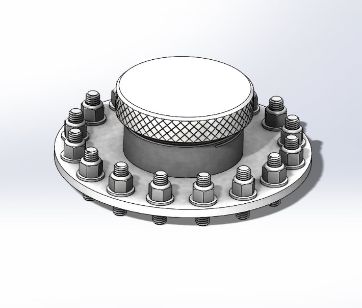
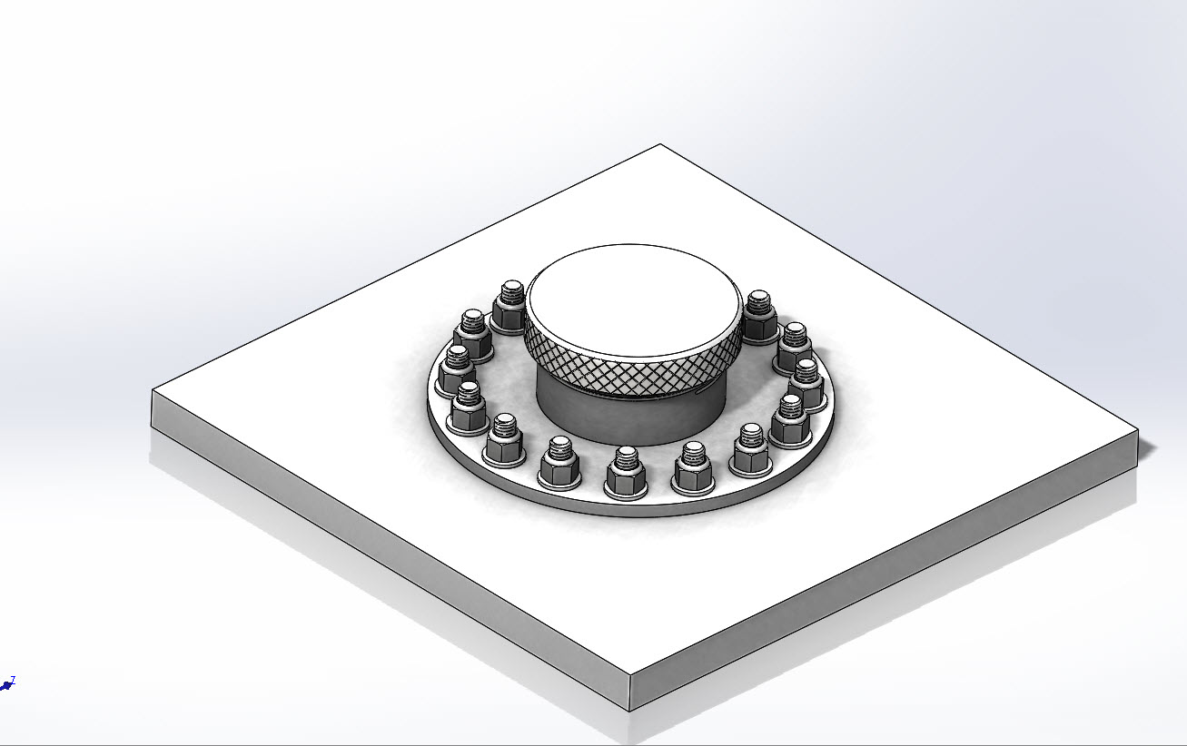
To begin this process, a simple setup assembly is created. This assembly is used to identify each extra part and feature that will be tied together. A “Base” component that represents the container is placed into the assembly first. The fill plate is then inserted along with the extra parts. Mates between these parts and the fill plate will define how it is arranged in the future assemblies. Editing the base part, in the context of this setup assembly, allows us to create the cut features that will be included in the Smart Component.
Add all related components to the setup assembly. This includes any parts that you would like to be inserted with the Smart Component when used in future assemblies. In this case we have 16 studs, 16 nyloc nuts, 16 washers, a fill cap, and a rubber O-ring.
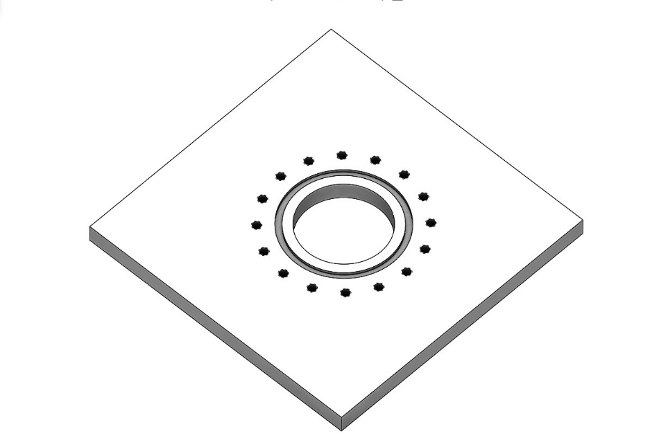
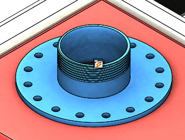
In-context features are applied to the base plate inside this setup assembly. In this example there is an inner cylindrical through-cut, a groove cut for the O-ring, and 16 tapped holes for the studs.
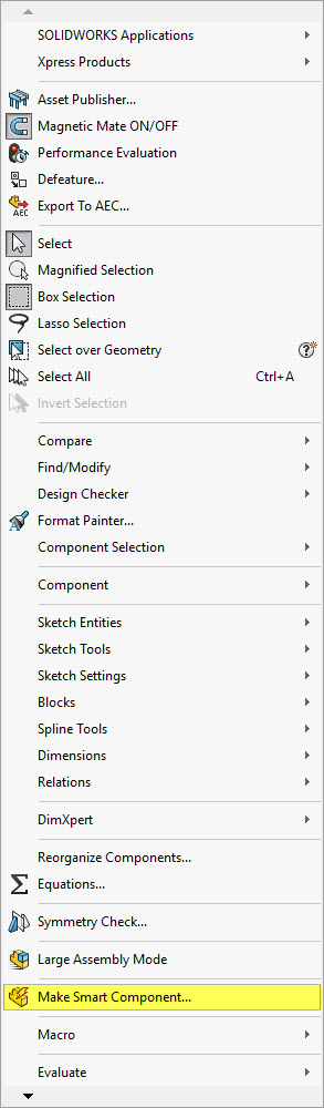
To turn this into a Smart Component, the “Make Smart Component” command is found on the TOOLS pull down menu. This is done while you are still in the setup assembly.
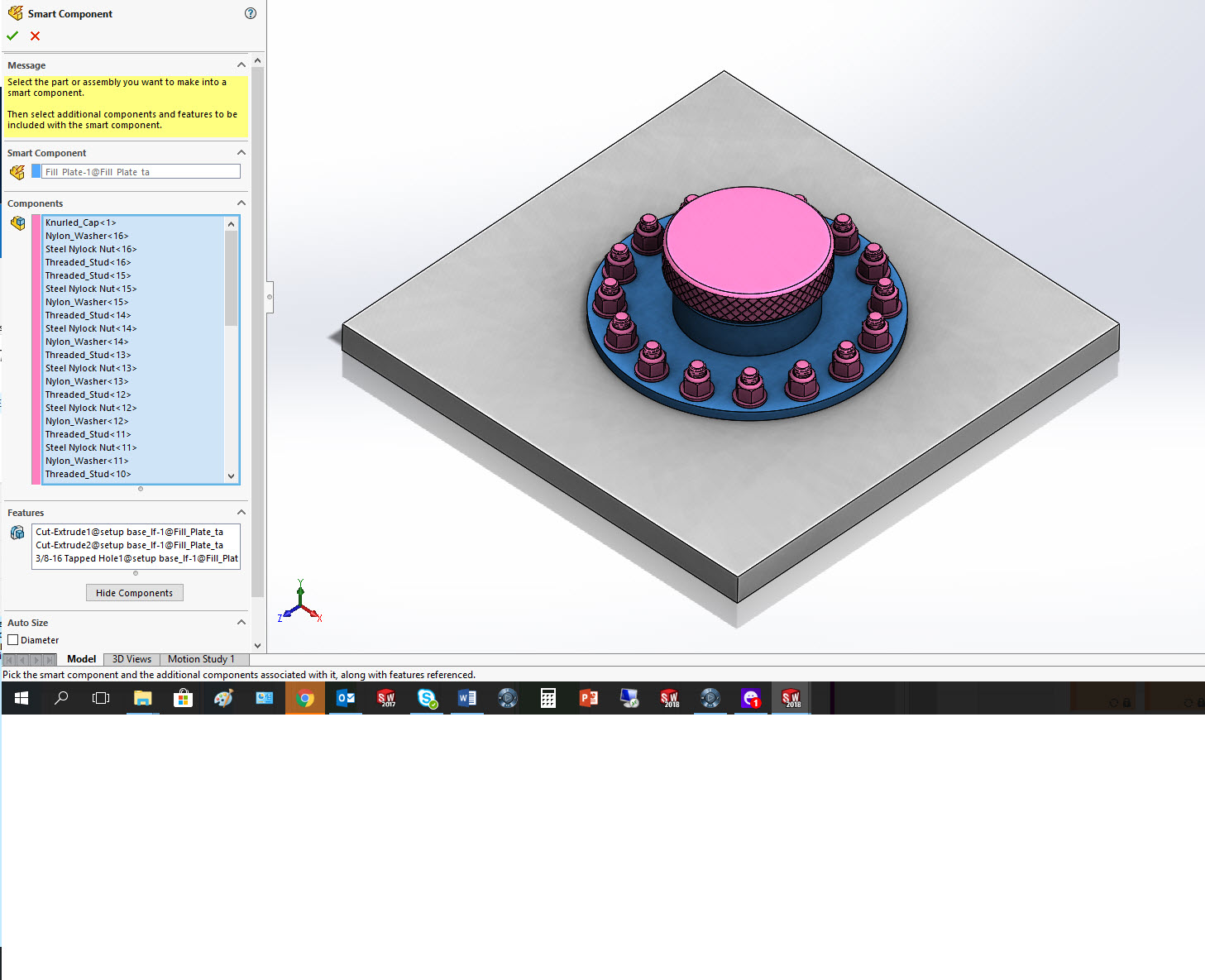
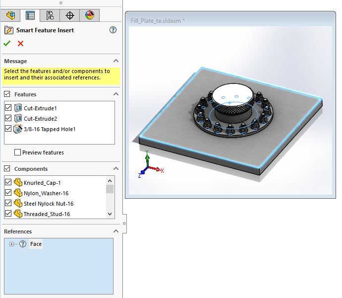
The interface for defining the Smart Component is straight forward. You need to identify all the components that you would like to be inserted with the part, as well as the in-context features.
To use this smart component in future designs, simply place the fill plate and mate it in your assembly just like any other component.
Selecting the component from the feature manager will show the Smart Component icon on top of the part.
Clicking on this button will bring up the Smart Component interface. The preview window will show the setup assembly that we used to define the Smart Component. Select the face in your assembly that matches the face of the setup assembly. This is identifying which face/component to apply the cut features to. You can unselect some of the features and components if you do not desire for them to be inserted or applied in this specific assembly.
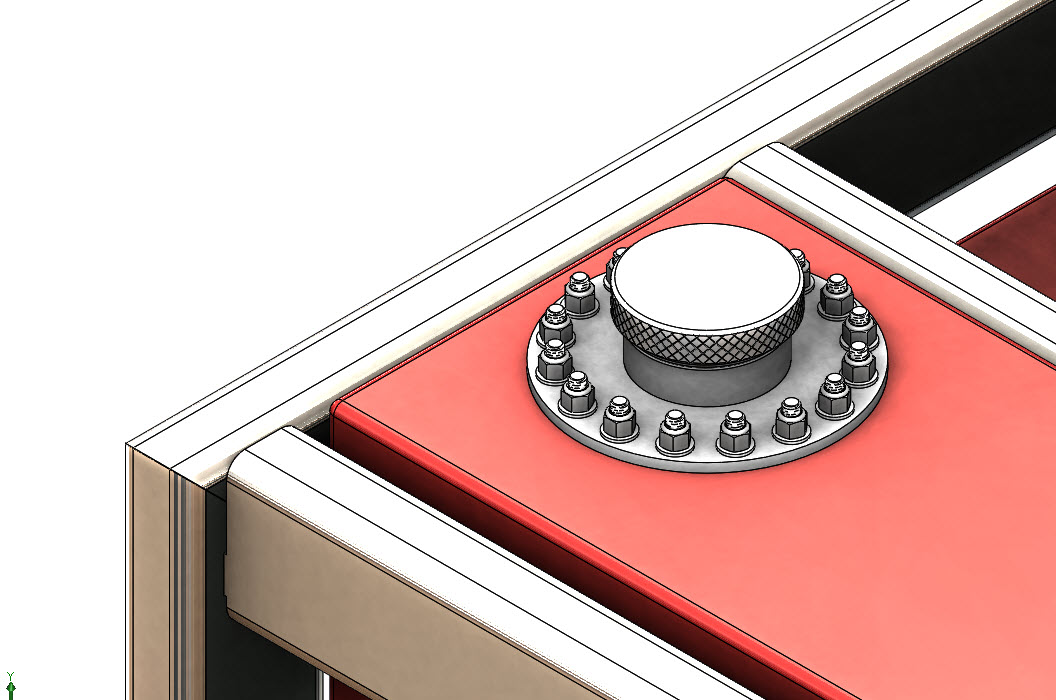
Once complete, these components are inserted into the assembly and the in-context features are applied to the selected part file.
A simple exploded view shows the parts and features that were inserted.
These cut features are still tied to the smart component and will move and update with the fill plate if the locating mates are adjusted.
Smart Components are easy to setup and easy to use in SOLIDWORKS. They reduce a lot of the repetitive tasks on similar designs. Smart Components also make sure the same parts are being used, guaranteeing consistency between projects. It’s time to work smarter, and give Smart Components a try!
Greg Buter
Senior Application Engineer
www.cati.com