Y Up, Z Up, Why Does Z Matter in SOLIDWORKS?
SOLIDWORKS is built around a Y Axis Up orientation and that’s fine when you deal only in SOLIDWORKS, but what about other apps that need to work with SOLIDWORKS data? What seems like a small discrepancy can cause quite a bit of pain and no fun in other apps. So if you’re in this scenario, don’t worry this blog will walk you through a few workflows to consider to help ease that pain.
Some companies know they’re going to be dealing in the Z-Up world moving forward, like maybe moving to a platform where the world is built around Z-Up or a CAM package where Z-Up is the standard. The first thing you should do is stop making parts and assemblies with a Y-Up template.
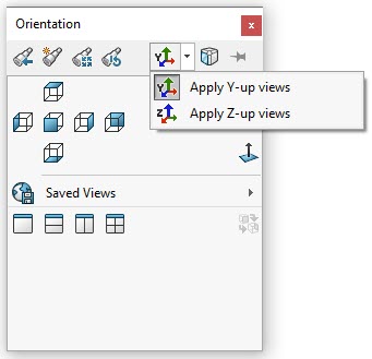
To build a Z-Up template, you’ll need to start with a blank part or assembly from your original templates. Then re-orient the Z Axis Up. The easiest way to do this beginning in 2020 is to use the “Apply Z-up views” option from the View Orientation Dialog Box (Spacebar or View > Modify > Orientation).
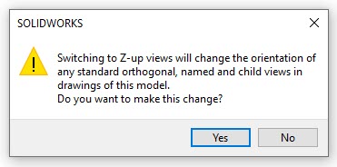
You will be prompted that orientations of any standard orthogonal, named and child views in drawings will change as well and you would select ‘Yes’. Don’t worry about that for now, we’ll discuss those ramifications in a minute.
Next you will have to rename the standard planes to match their corresponding views.
Front Plane: rename to ‘Top Plane’
Top Plane: rename to ‘Right Plane’
Right Plane: rename to ‘Front Plane’
Now views and primary planes should be in sync. And at this point you are ready to save your template. This will need to be done for your part and assembly templates and should be what’s used moving so you don’t create more Y-Up models.
So far, not too painful. Now let’s talk about the fun part. What about your legacy data? Earlier I mentioned the prompt that appears when changing to Z Axis Up which informs you that the views will change. As the prompt says, if you execute the axis change the views on your drawing will be adjusted for this new world, which could throw off already created drawings.
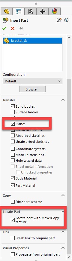
If you have a part file and a drawing file and you’re happy already with the orientations, but the other system you’re interacting with is Z-Up, it may be worthwhile to create a part solely for the purposes of the Z-Up environment. Now I’m not saying re-model the part, but what you can do is create a derived part by using Insert > Part from a blank Z-Up part template.
You can even use the “Locate Part with Move/Copy feature” to help orient the part based on the views you want to achieve in your secondary system as well. And you’ll want to add “Planes” as part of the transfer as well.
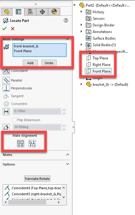
During the ‘Locate Part’, if you see only Translation and Rotation options available, select ‘Constraints’.
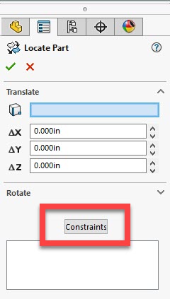
Then select a primary plane visible in the graphics window of the part and a primary plane from the new part’s template in the design tree and select ‘Add’. You can use ‘Mate Alignment’ as well to flip the orientation as necessary.
Once done, you’ll have a part that looks right and can be used in your Z-Up world, without interfering with any drawings from your Y-Up world. And to top it off, the new part you’ve created is parametric to the first, so any changes will propagate throughout both!
Hope this helps!
Brandon Nelms
Sr. Application Engineer Team Lead
Computer Aided Technology, Inc.