Tips for New SOLIDWORKS Users Part 3: Fully Define, Every Time
Welcome back to our series of tips for new SOLIDWORKS users. As I mentioned  in my last blog, I started teaching SOLIDWORKS CAD software to both new and experienced students in 2001. This blog series covers three great tips I’ve learned over the years to help new SOLIDWORKS users get started off on the right foot:
- Always start your sketches the same way – and know when you are in sketch mode
- Keep your sketches simple
- Fully define, every time
Today, we will finish up by covering the final tip: Fully define, every time.
This tip is such an important part of SOLIDWORKS and such a valuable lesson that a few years ago I wrote and recorded a song on the topic. You can view the YouTube video of the song.
The SOLIDWORKS CAD software can be defined as a parametric 3D modeler. The term parametric can be thought of as “rules-based design”. The rules for your design are implemented and defined with the first sketch you create and continue through the entire design.
As an example let’s take a look at the following scenario:
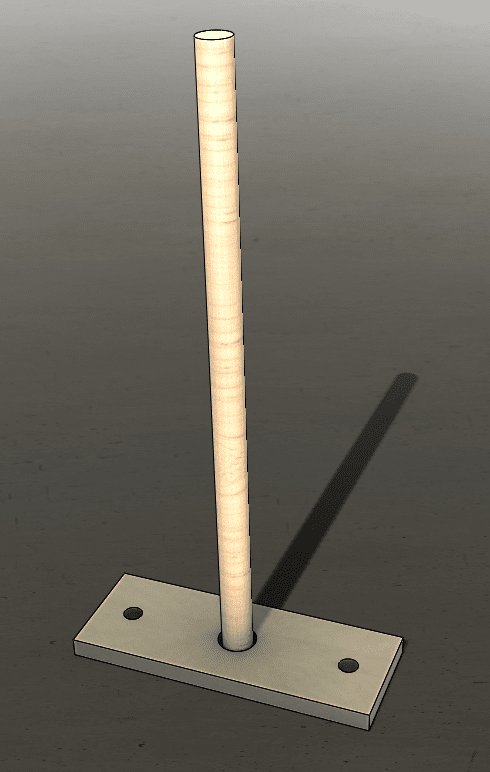
Figure 1: A wooden pole mounted in a steel plate with holes
In Figure 1 we see a wooden pole mounted in a steel plate. There are three holes in the plate – one in the center for the wooden pole and one on each end of the plate for .250 DIA mounting screws. The question is: How is this plate mounted? If there is a secondary component which has matching holes, then the center to center distance of these holes should be defined as follows:
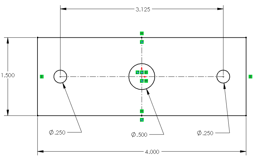 Figure 2: The sketch of the plate with center to center distance for the holes defined
If we create our sketch for the holes similar to figure 2 we will be specifying that the smaller .250 DIA holes will always have a center-to-center distance of 3.125. This number will be held regardless of the overall width of the plate.
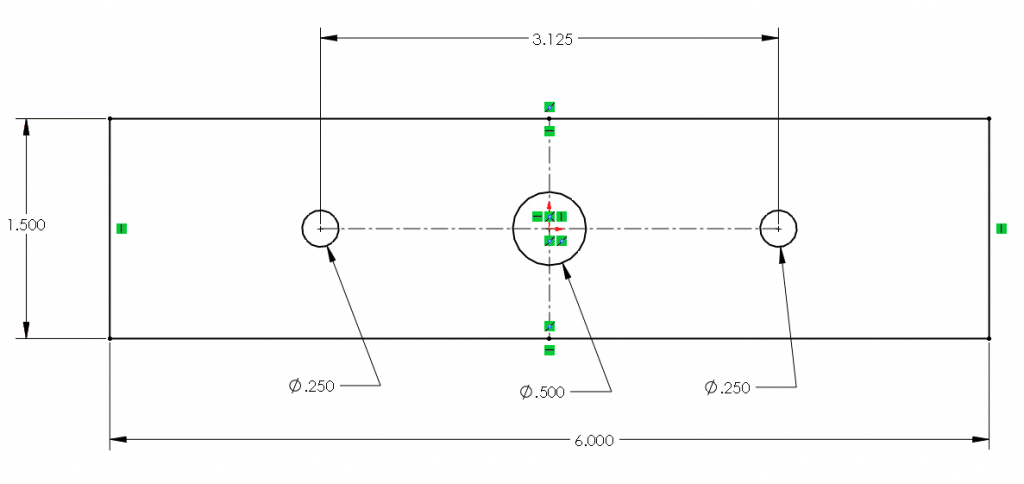 Figure 3: The overall width of the plate has increased from 4.000 to 6.000
As we can see in Figure 3 we have changed the overall width of the plate from 4.000 to 6.000, but the center-to-center distance of the .250 DIA holes has remained at 3.125. This was due to our dimensional rule. This dimensional rule would be appropriate if you were attaching this plate to an existing lower plate (or platform) which had pre-drilled holes. In this scenario, the center-to-center distance of the .250 DIA holes would need to be held so that the hardware would align to the pre-existing holes.
An alternate way to apply rules to this sketch would be to define the distance between the edges of the plate and the center of the holes.
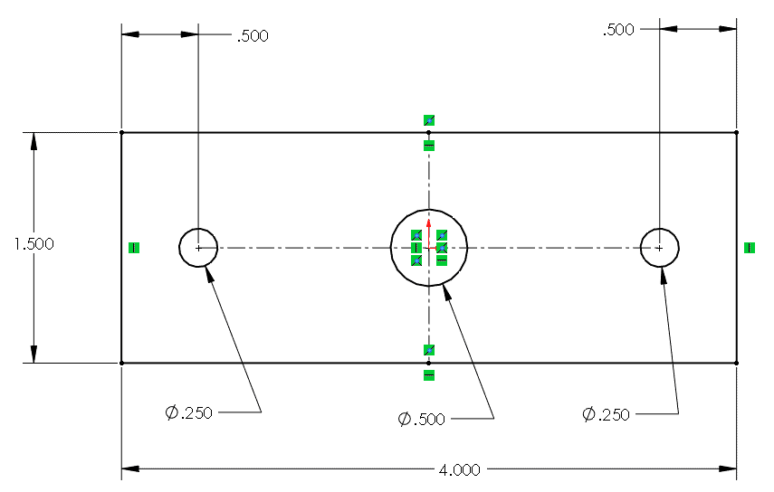 Figure 4: The sketch of the plate with the holes defined at .500
from each end of the plate
If we create our sketch for the holes similar to figure 3 we will be specifying that the smaller .250 DIA holes will always be .500 relative to each end of the plate. The center-to-center distance of these holes will change as the width of the plate increases or decreases.
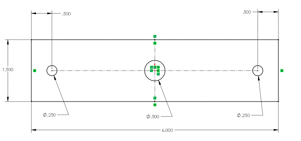 Figure 5: The overall width of the plate has increased from 4.000 to 6.000
As we can see in Figure 5 we have changed the overall width of the plate from 4.000 to 6.000. This time we created a rule that says that the .250 DIA holes must remain .500 from each end of the plate. Therefore, changing the width of the plate from 4.000 to 6.000 causes the .250 DIA holes to change position. This type of rule would be more appropriate when working in a scenario where the plate is being mounted to a block of wood which does not have pre-drilled holes, using self-tapping wood screws. In this scenario, it wouldn’t matter that the center-to-center distance of the .250 DIA holes is changing, since there are no pre-drilled holes in the wooden block.
Finally, we can take a look at an example where the sketch is not fully defined, and instead is left under defined.
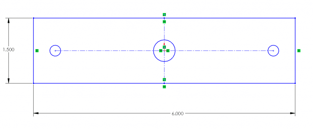 Figure 6: The sketch of the plate and holes has not been fully defined
In the previous 2 examples, we were able to examine the sketch and predict what would happen when we change the width of the plate, based on the rules assigned to our fully defined sketch. When we fully define our sketches in SOLIDWORKS we make them predictable. But what about the sketch in Figure 6? What is going to happen to the holes when we change the width of the plate from 6.000 to 4.000? The answer to this question is “We don’t know!” That’s the problem with underdefined sketches – we don’t know what’s going to happen when we change a dimension because we haven’t defined all the rules that govern that sketch. This will lead to rebuild errors which can often be confusing and time-consuming to resolve.
When it comes to sketching in SOLIDWORKS, remember this great tip: Fully Define, Every Time. A fully defined sketch will be a predictable sketch. You can make changes to your sketch and know ahead of time how the remainder of your model is going to react to these changes.
Related Articles:
- – Tips for New SOLIDWORKS Users Part 1: Sketch Mode
- – Tips for New SOLIDWORKS Users Part 2: Keep Your Sketches Simple