Sheet Metal Parts in a Flash!

I talk to a lot of SOLIDWORKS users that RUN away from Sheet Metal design because they think only a SUPER HERO could possibly do the work. Once they learn how to use SOLIDWORKS’ Convert to Sheet Metal tool, they see just how fast and easy Sheet Metal design is in SOLIDWORKS and hopefully by the end of this blog you’ll CONVERT too. If you’re already sick of the puns, guess what…it’s only going to get worse from here! So let’s get busy and Fold! Barry! Fold!
To be a “Sheet Metal” part in SOLIDWORKS there are three requirements:
1) Has to be thin walled
2) Has to have “bends” at the corners
And most Importantly in my opinion
3) Can be flattened
But just as a Barry Allen didn’t start out as the Flash, a SOLIDWORKS part doesn’t have to start out as Sheet Metal Part. If you’re reading this you know how to make basic extrudes in SOLIDWORKS right? Take a sketch and extrude it:
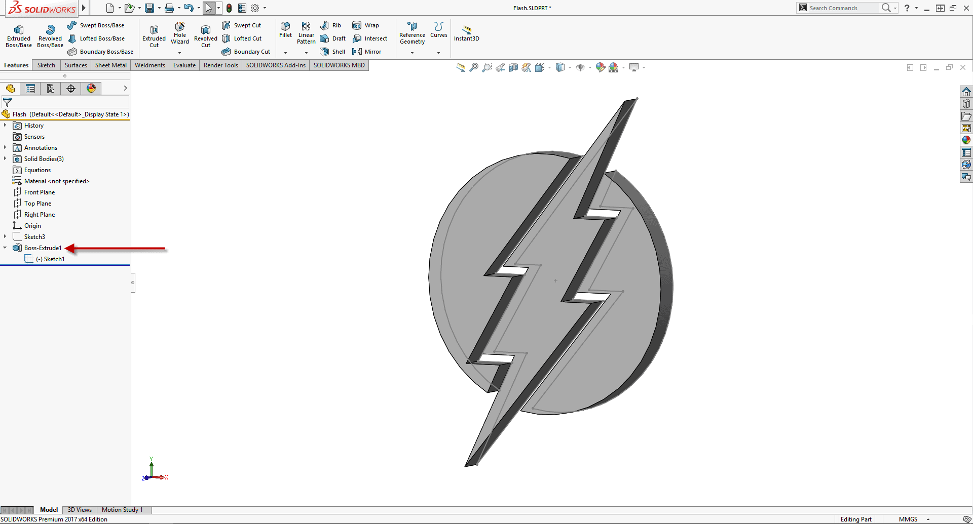
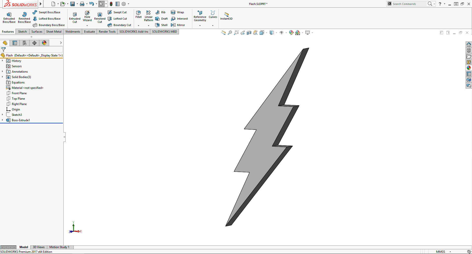
For the purposes of this blog I’ll hide everything but the lightning bolt body.
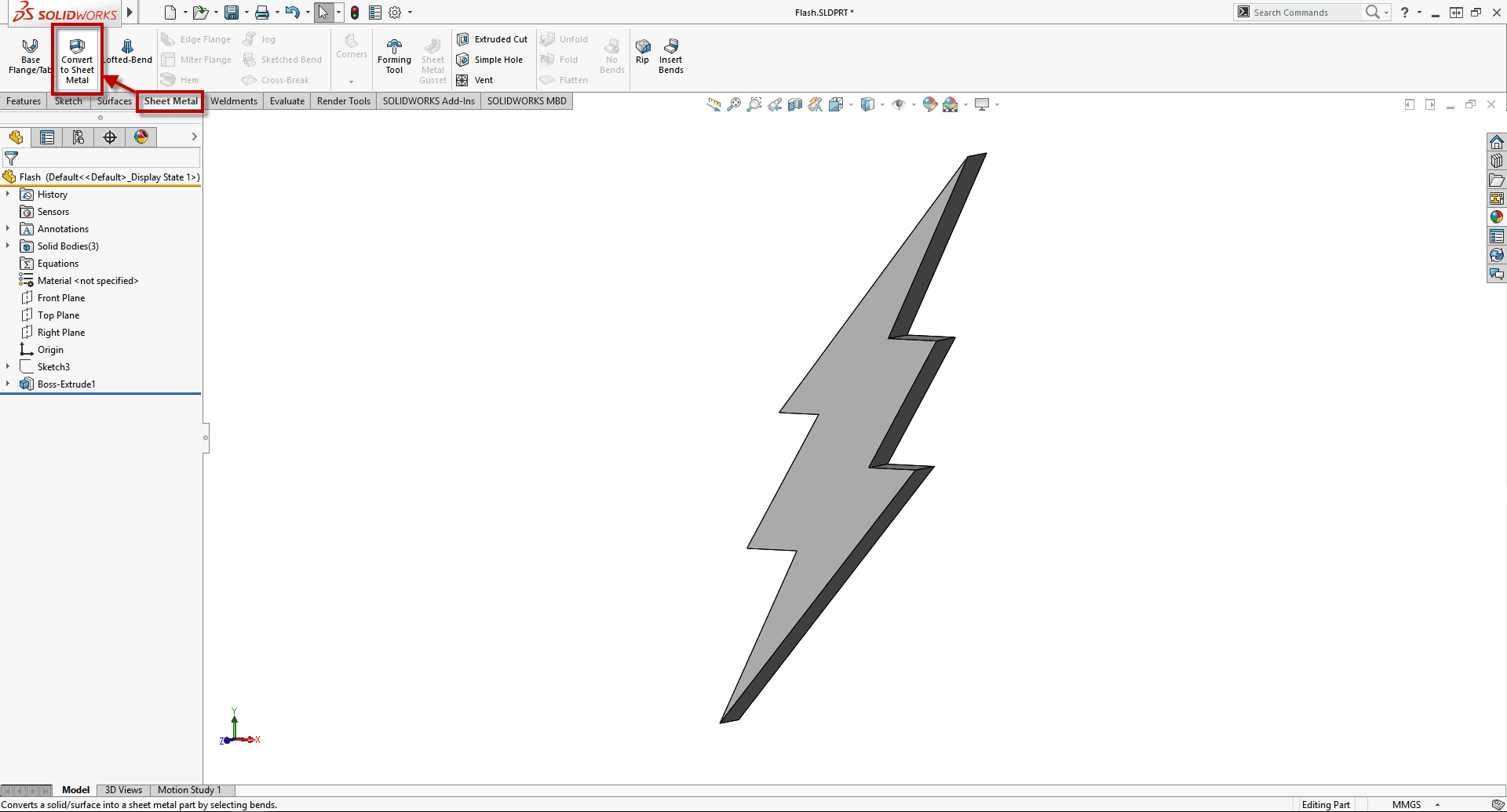
Then from the Sheet Metal Tab on the Command Manager I can use the power of CONVERT TO SHEET METAL (or you can use the file menus: Insert > Sheet Metal > Convert to Sheet Metal, but what is this the 50’s?)
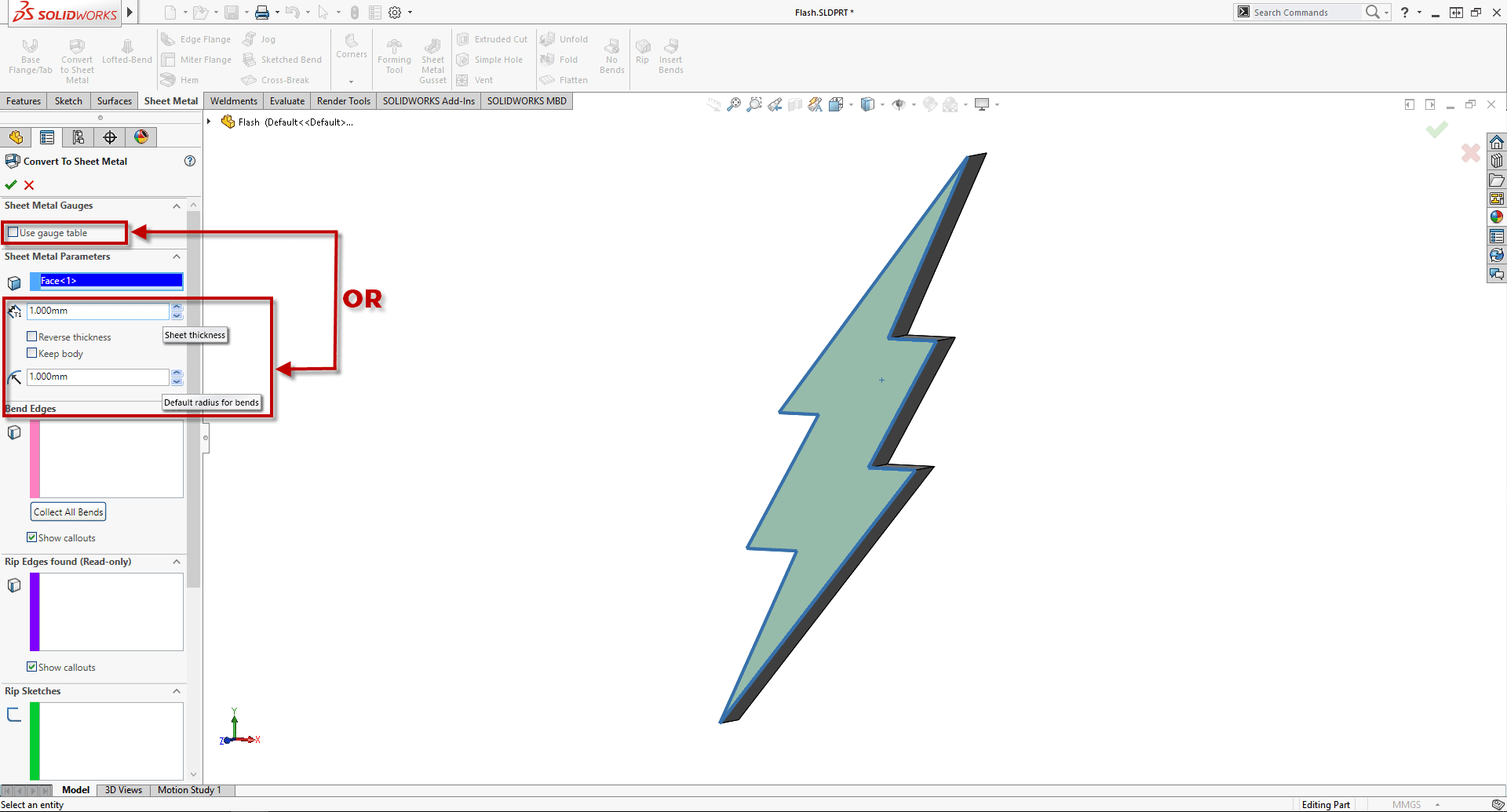
First I have to pick a face to be fixed. This is where all my other folds are going to come from:
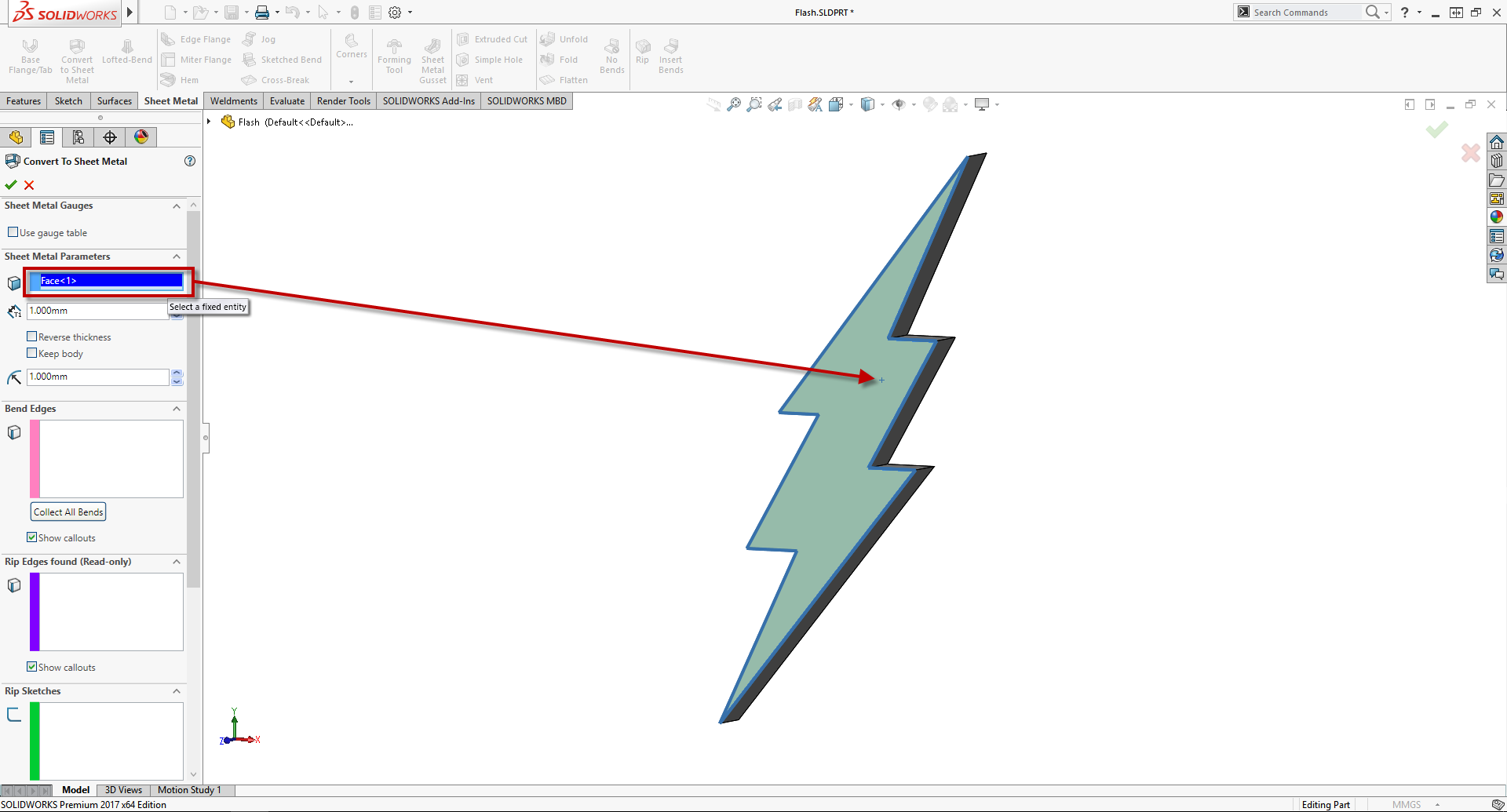
Then I need to determine what size sheet metal I am going to use. This can be done with either the Gauge Tables or putting parameters for thickness and bend radius:
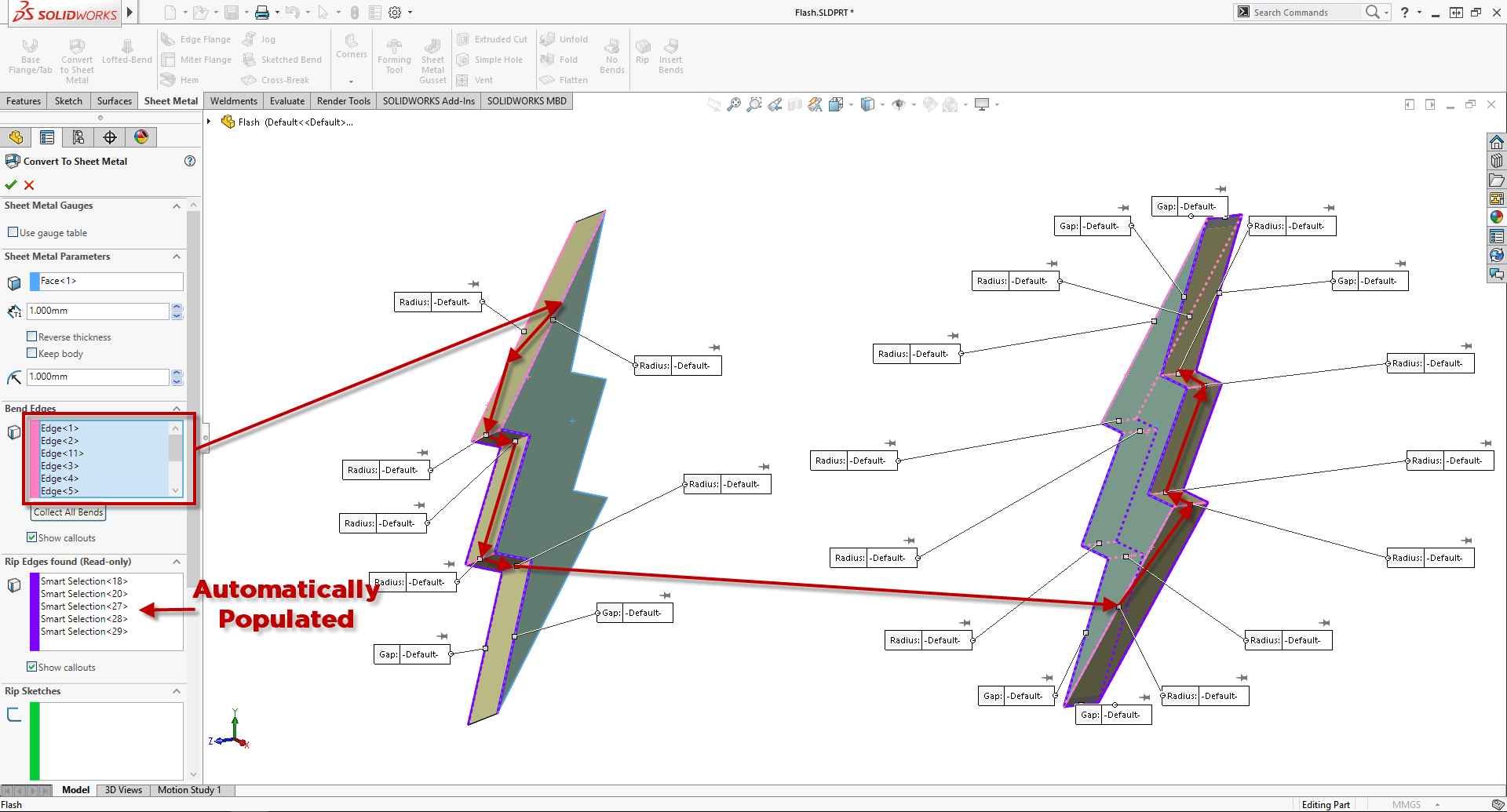
Now it’s as easy as clicking the edges one after another to bend sheet metal around my part (or inside even! with “Reverse Thickness”). As I select my bend edges SOLIDWORKS automatically puts in the necessary rips needed to make the sheet metal part.
Click! Barry! Click!
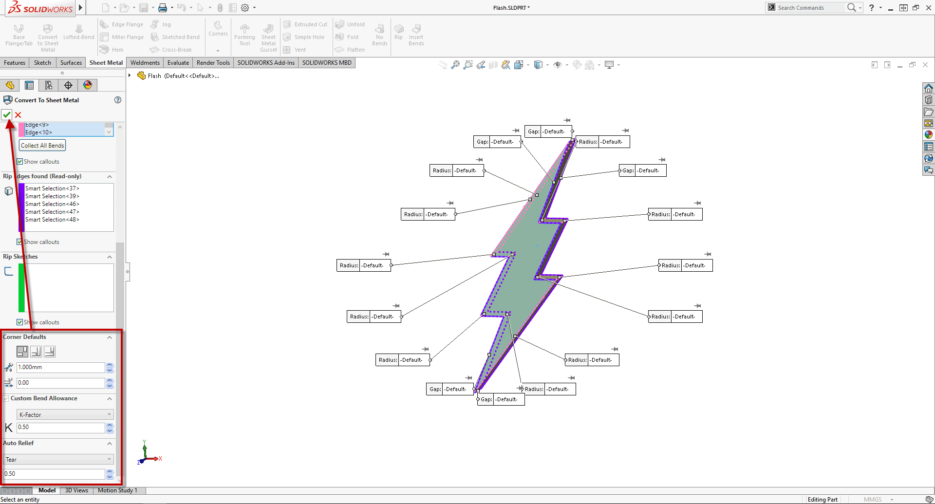
Lastly we specify defaults for Rip Gaps, Overlaps, Bend Allowance, and Auto Reliefs. These can be over-ridden later if needed on an individual feature basis, but it is a good idea to try and use the values you’ll want for most of your downstream features.
It’s almost like it happened in an instant! We can now easily get our Flat Pattern:
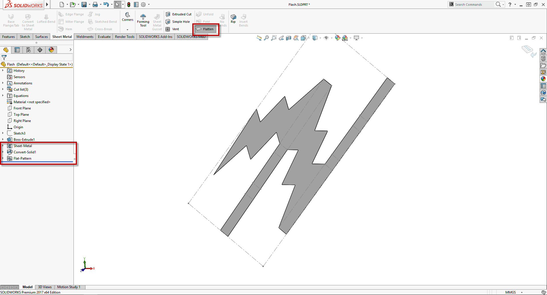
This is 100% how enclosure design should be done. Design your enclosure block, then wrap it up in Sheet Metal. Maybe even design that Block with references to the components I want to be sure and cover. Once you have a Converted Sheet Metal part you can continue to add additional sheet metal features to the part (like hems, gussets, etc), but using the Convert to Sheet Metal tool allows me to change the block size and update my sheet metal flat pattern in an instant with little effort, which is really what I’m after.
That’s a Sheet Metal part in a FLASH!
Brandon Nelms
Application Engineer
Computer Aided Technology, Inc