SOLIDWORKS 2018 What’s New – SOLIDWORKS Electrical Project Level Attribute Styles, Symbol Editor – #SW2018
SOLIDWORKS 2018 What’s New – SOLIDWORKS Electrical Project Level Attribute Styles, Symbol Editor – #SW2018
Project Level Attribute Styles
In SOLIDWORKS 2018, editing the way you want your attributes to appear on your schematic has never been easier. In the past if you wanted to change how all of your component marks were displayed – such as making them blue– you had to open up every single symbol in your schematic and edit the properties of the Mark attribute. Now you can specify at the project level that you want a certain look to apply to all Mark attributes wherever it is used in the project.
To do this, open up the Project Configuration dialog box and select the brand new Attribute tab. You can select pre-existing attributes using ‘Add symbol attribute’ or ‘Add title block attribute.’

Symbol Editor Attributes
There’s also been some helpful changes to the attributes when you are editing a symbol. There are a number of new commands.
Replace Attribute – Select the attribute to replace, and then the attribute window you are familiar with will open up. You can select any attribute to replace the one already placed in the symbol.
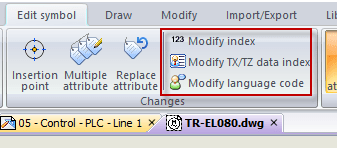
Modify Index, Modify TX/TZ data index, Modify language code – These will allow you to modify an existing attribute to a different index, depending on which attribute it is. For example, a user data field attribute may be showing User Data 1, but you want to show the 3rd User Data field. You would modify the index to 3. Or maybe there is an English language description attribute that you want to change to the French attribute. You would use the modify language command.
Passive Symbols
In all symbol properties there are fields to specify a default manufacturer part to attach when inserting the symbol into a schematic. It doesn’t make sense to utilize that for passive symbols. Those are the symbols you draw that don’t contain any circuits, connection points, or attributes. They are just a drawing to place on the page. Now, the Manufacturer Parts, Characteristics, and Options fields are unavailable in the properties dialog box for those symbols.
I hope this part of the What’s New series gives you a better understanding of the new features and functions of SOLIDWORKS 2018. Please check back to the CATI Blog as the CATI Application Engineers will continue to break down many of the new items in SOLIDWORKS 2018. All of these articles will be stored in the category of “SOLIDWORKS What’s New.” You can also learn more about SOLIDWORKS 2018 by clicking on the image below to register for one of CATI’s Design Innovation Summits.
Brian Cooke
Electrical Application Engineer
www.cati.com