SOLIDWORKS MBD: Adding Balloons to an Exploded View
SOLIDWORKS MBD is a wonderful tool for creating electronic representations of your designs that can be shared with fabricators and customers. You can create multiple 3D views with Geometric Dimensioning and Tolerancing (GD&T), datums, as well as customize your 3D PDF to include custom properties and bill of materials(BOMS).
In many cases it can replace traditional drawings! Which are limited to two dimensional views of the model or assembly.
Today I want to show you how to add balloon annotations to an exploded configuration and capture it with SOLIDWORKS MBD.
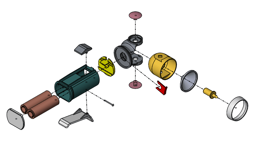
First you will need to create an exploded view of your assembly. NOTE: It will look nicer if you include the explode lines.
Before you can add the balloons, you will need to create a BOM. From the Assembly tab of the command manager select “Bill of Materials”.

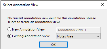
Use the bom-standard template and “Parts Only”. When you click OK you will be prompted to select an annotation view, select “Existing Annotation View” and “Notes area” then click OK.
Place the BOM table in the graphics area. Open the Tables folder in the Feature Manager Tree and RMB on the Bil of Materials and select hide.
Next you will need to create an annotation view, so the balloons will be facing correctly.
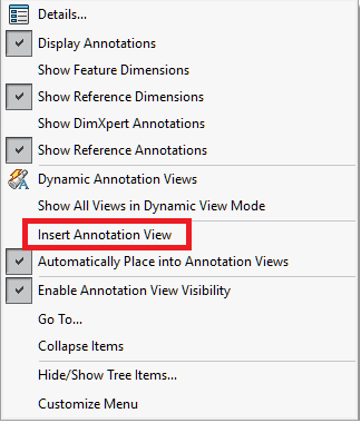
With the exploded view in the isometric orientation, RMB on the Annotations folder and select
“Insert Annotation View”, then select *Isometric from the list and click “OK”
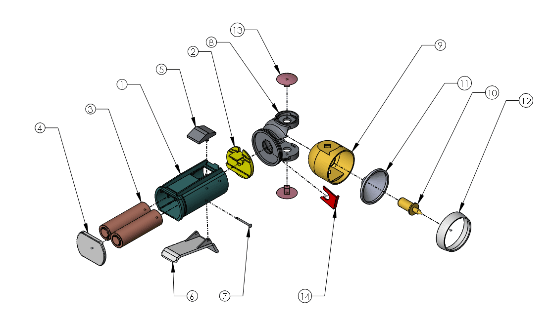
Next go to the Insert menu and select Annotations – Balloon. Then begin to select each of the items and add the balloons.
Hold down ctrl (Command ⌘) and select each balloon. Then use the “More Properties” button to show the leader style to make changes.
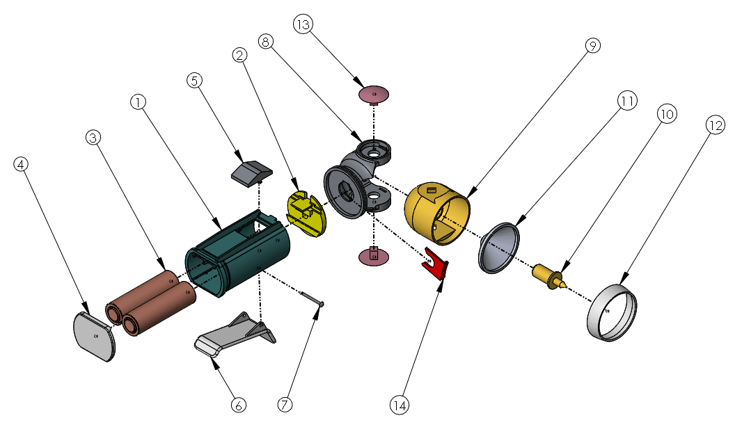
Since there are no Magnetic lines in the assembly it might be helpful to create a 3D sketch and construction lines to use for the alignment of the balloons. 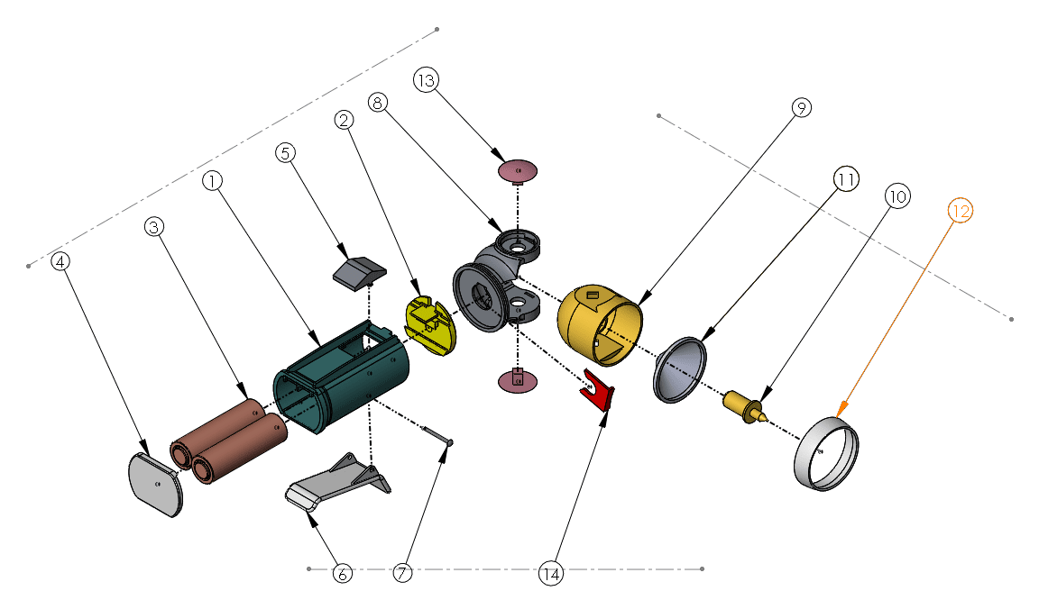
The balloons won’t snap to the lines but using them as guides will help make the view neater.
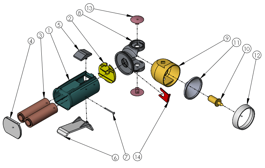
After manually aligning the balloons you can hide the sketch.
Next select the 3D Views tab at the bottom of the screen. Go back to the default configuration and hide the assembly annotations.
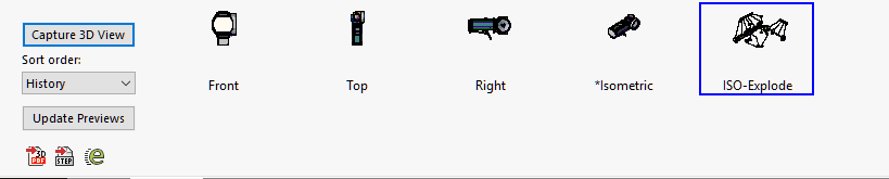
Orient the view to the Front, Top, Right, and Isometric views and use the Capture 3D view button to create and name each view.
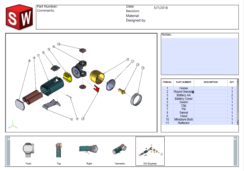
Activate and explode the exploded view and show assembly annotations. Then use the Capture 3D view to create and rename the view to ISO-Explode. The 3D views will look like this.
The final step is to click on the “Publish to 3D PDF” button on Command Manager, MBD tab.

Select an assembly template to use, and all the views to be included in the PDF and click OK. Next save the PDF to disk and open or select “View PDF” when in the Save As dialog.
This is what your PDF will look like.
If you need to learn more about SOLIDWORKS MBD please read our other blog articles:
- Capturing 3D Views in SOLIDWORKS MBD
- Using eDrawings with SOLIDWORKS Model Based Definition (MBD)</li
- SOLIDWORKS MBD: The next step in the evolution of part definition
- SOLIDWORKS: MBD Template Editor – Adding Custom Properties
Thank you,
Dennis Barnes
Applications Engineer
Computer Aided Technology, Inc