SOLIDWORKS Sheet Metal: Bending Basics
Of all concepts in sheet metal design, bending and flattening are two of the most fundamental and important to understand. In this blog article, we will look at the basic theory behind sheet metal bends, particularly the Bend Allowance (BA), and how to apply this knowledge when utilizing SOLIDWORKS sheet metal tools.
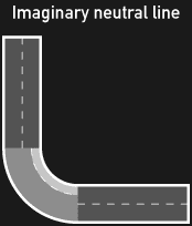
The main concept revolves around the idea of a “neutral axis”. When a piece of sheet metal is bent, the inside radius material at the bend region is compressed, while the outside radius material is stretched. It is important to keep in mind that there exists a central plane of metal near the center of thickness that remains unchanged – no compression or stretching. You can look at it like a piece of paper that bends but doesn’t deform.
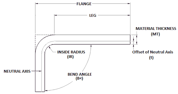
Ideally, the neutral axis exists at the center of the material thickness. However, in real-world bending scenarios, it is always off-center a little; never exact. Since we can’t really know where the neutral axis actually exists after a bend, we need to use approximations to make our best guess so the final flat pattern length can be predicted.
This is where the term correction factor (k-factor) comes in. The k-factor is a ratio of neutral axis offset to the material thickness. It can theoretically take a value of zero to one, inclusive, but is usually somewhere around 0.40 to 0.55.
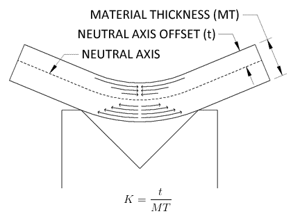
The k-factor value is experimentally determined for based on given material, thickness, bend radius, and bending method. Each factor, and more, affect this estimated value. Since it depends on several factors, tables of empirically determined k-factors have been created for reference. K-factor is used in other bend calculation formulas, most notably, Bend Allowance.
The Bend Allowance (BA) is the arc-length of the neutral axis through the bend region, and is one of several preferred methods in determining overall flattened length.
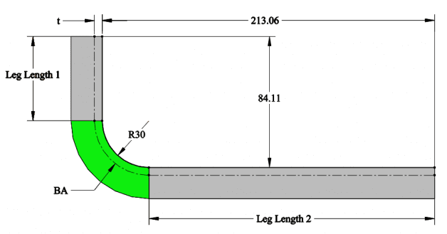
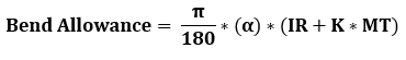
Where α is bend angle, IR is internal radius, K is k-factor, and MT is material thickness.
In the figure above, we would simply calculate the overall flat length as L1 + BA + L2.
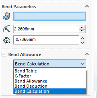
In SOLIDWORKS, there are several options available for BA. Bend Table templates are available for users to input custom bend parameters. If the k-factor is known, SOLIDWORKS will insert this value into the Bend Allowance equation and update the part accordingly. If a pre-calculated BA is known, this value can be input directly as a parameter for SOLIDWORKS to use.
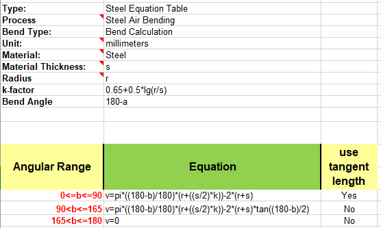
Finally, Bend Calculation is available for users who want to input specific bend angles, bend radii, and material thickness values into the formulas below and have SOLIDWORKS determine the developed length. In the formulas, “v” represents compensation factor which is just SOLIDWORK’s best estimation of the flattened bend region length. The catch here is that k-factor cannot be modified in the formula. SOLIDWORKS has this hard-coded into the system.
I hope this article gave a little insight of what’s going on under the hood to generate flattened lengths. Happy sheet metaling!
James Carlin, CSWE
Computer Aided Technology, Inc