DESIGN FOR 3D PRINTING - Tips, Tricks, & Techniques Part 3 of 3
Designing for Additive Manufacturing can be somewhat different than designing for traditional Subtractive processes (Mills, Lathes, etc.) We will break this down into 3 parts that impact your design, Design Considerations (part 1), Exporting Data (part 2) and Part Printing (part 3).
In this blog let’s take a look at the next step – Part Printing. Part Preparation is extremely important to initiate the function in the equation of form, fit and function. We will also focus on understanding build times that contribute to the manufacturing schedule.
Build Orientation:
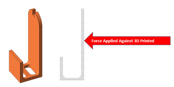
Build orientation will affect strength, supports and aesthetics. Since all Additive Manufacturing (AM) parts are built in layers, or rather 2 dimensional images stacked into a 3rd dimension, it is important to understand the mechanical stresses that will be applied to the part. Pressure at a specific layer can create a fracture at the layer faster than a part layered in a different direction. For example, consider the simple bracket below. Building it in a standing position could shear at a layer line if any force is applied to the side.
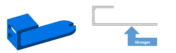
Therefore, for strength, laying the bracket down rather than standing up could provide better mechanical strength.
Also, orienting a part in the lowest Z-height is often considered the fastest build speed. While this is often true, there are exceptions, part geometry is not the only factor to consider. You must also consider the build process of the 3D printing technology. Our same simple bracket built with FDM (Fused Deposition Modeling) technology is just such an exception.
Since FDM technology uses 2 separate extrusion tips for independent support and model materials. This means each extrusion tip must deposit both materials individually on each layer as required. Consider positioning your part where less support is required at each layer and therefore only the model material extrusion tip is used and can considerably reduce the time.
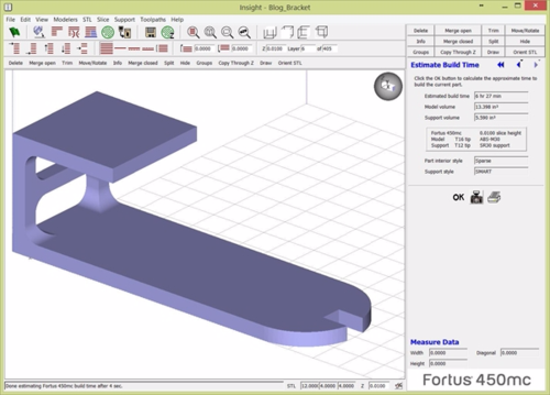
Both parts at (12 x 4 x 4 inches) when processed on a Stratasys Fortus 450mc with the same parameters (.010 layers, sparse fill, normal surface and SMART supports) yield surprising results. While the bracket standing up is 3 times taller, it takes almost an hour less build time. See results below:
Positioned in the shortest Z-axis the build time is estimated at 6 hrs. 27 min.
Positioned up and using less support material, the estimated build time is 5 hrs. 32 min.
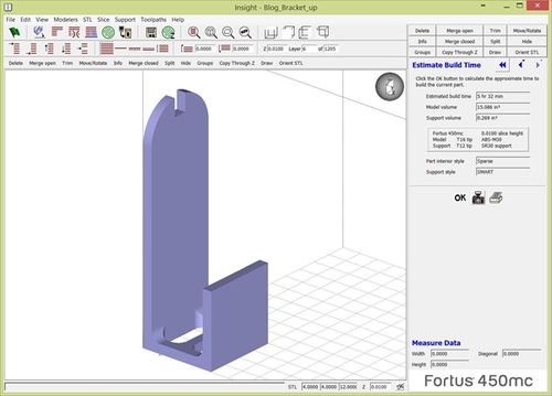
The reason for the time savings is because in the lowest Z-axis orientation the support extrusion tip and the model extrusion tip must take turns depositing material for 300 layers. While standing the bracket up there are no shared layers of support and model material saving the time of switching between the two extrusion tips to print the part.
However, you must evaluate all requirements of the part, not just build speed, such as strength mentioned earlier. Surface quality or aesthesis can be another important factor to how you position your part.
‘Stair-stepping’ is caused from stacking 2D layers into a 3D shape. Just like the stairs in your home, there is a ‘Rise’ and a ‘Run’.
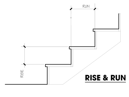
When the ‘Run’ becomes larger than the ‘Rise’ the offset is more pronounced. Orienting a part so the Rise & Run are equal (45o) or less (steeper) will aid in the surface finish and reduce hand labor of post-processing. A part with an organic shape will often show more pronounced stair-stepping or layer lines if not positioned well.
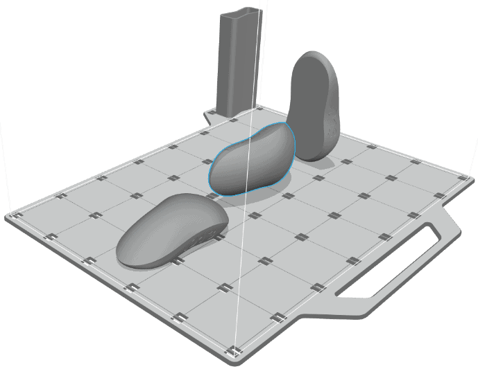
For example, the mouse below is built in 3 different orientations, all at the same layer thickness. The mouse on the left will show significant layering with a long ‘Run’ while the mouse on the right will have the best surface finishing aesthetically with a short ‘Run’. Note, the ‘Rise’ is a constant, for this example it is the layer thickness. While it may take longer to build, the time and cost saved in the hand labor of sanding the surface will be more than the increased build time.
Build Times:
We have already discussed above how positioning can affect build times depending on the technology. Let’s take a quick look at the build time comparisons on different technologies with a single or multiple part. For our comparison, we will use the same part.
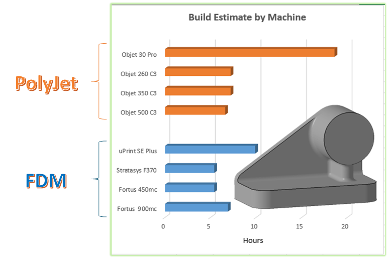
Comparing 2 popular technologies, PolyJet and FDM and 4 different machines of each technology, you can see the build times of a single part.
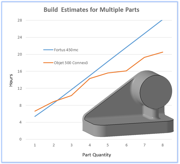
When comparing multiple parts, as shown below you will notice that the FDM is a constant linear time increase, whereas the Objet time spikes after 3 parts. With this particular geometry the Objet 500 Connex3 can run 3 parts on a row, therefore there is only a slight increase between 1 – 3 parts, as a 4th part is added a new row is created and the build time jumps because the print head indexes to create an additional row. Again, there is only a small increase between 4-6 parts and another spike as a 3rd row is created for the 7th part.
Summary:
This concludes our 3 part series on Designing for Additive Manufacturing; Design Considerations (part 1), Exporting Data (part 2) and Part Printing (part 3). These are the building blocks of mastering 3 D Printing to its full extent. Happy 3D Printing!
Mark Abshire
Sr. Application Engineer, Additive Manufacturing
Computer Aided Technology, Inc