In Depth Reverse Engineering Workflow Part 2 : Scan to CAD
In the first part of this two part post, we took a look at the process for creating a 3D printable STL file from our scan mesh. This is great if you just need a copy of the part with no editing necessary. But what if you do want to edit the part? Then we will need to dive a little deeper into the realm of scan post-processing, and with a little extra elbow grease, we can create a parametric CAD file from our scan mesh.
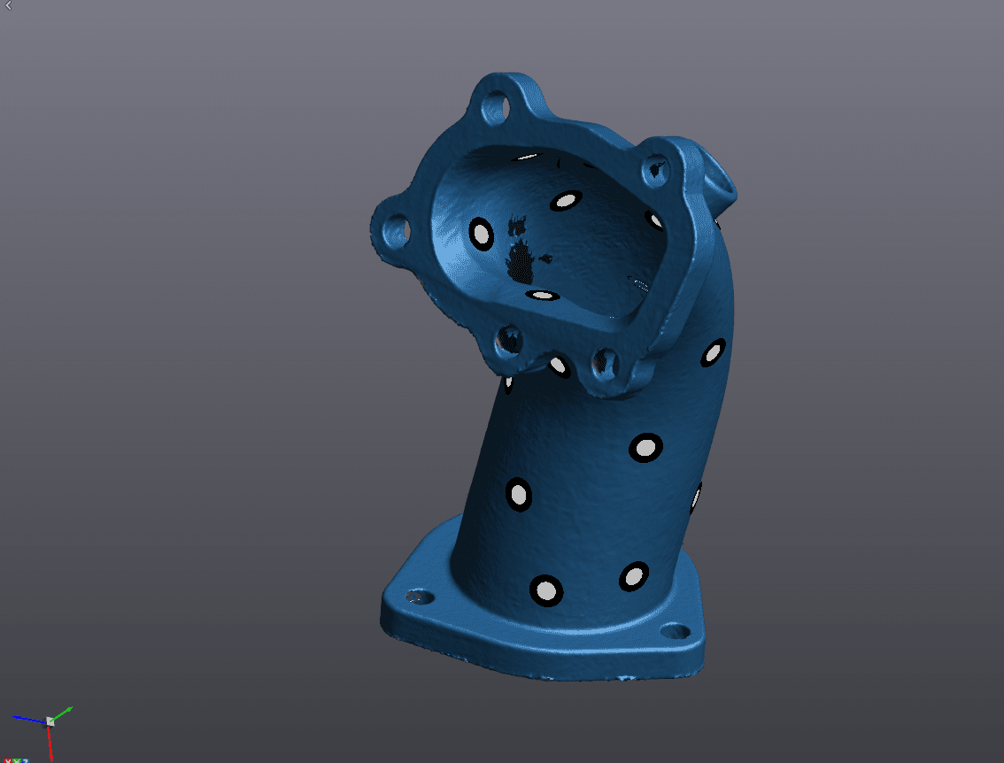
Starting where we left off in the last post with our cleaned mesh, we will begin extracting all of the necessary entities to port over to our CAD software. I’ll be using SOLIDWORKS here. This is really the secret sauce of the VXModel software. CAD programs like SOLIDWORKS need perfect equation driven entities in order to function. They struggle parsing the kind of files that come out of 3D scanners. This is because the scanners create what we call an “organic” mesh files, as opposed to the parametric files CAD programs are used to dealing with. What this means is that the scanner picks up what is put in front of it, namely all of the real-world defects that are present in the part will appear in the scan. Surfaces won’t be perfectly smooth, holes won’t be perfectly circular. So there needs to be a middle man software that can speak both parametric and organic, and that’s where programs like VXModel come in.
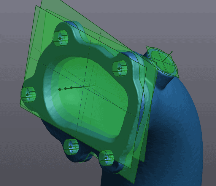
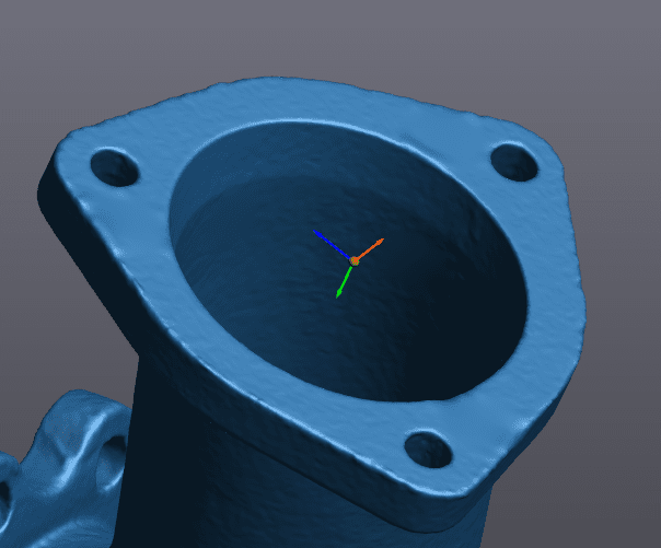
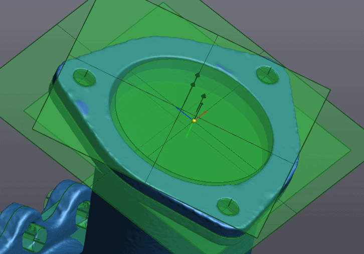
Back to our pipe part, we’ll begin by extracting the information needed to create our two flanges. These features can be defined by their front and back planes, a cross-section, and cylinders or circles for their bolt holes. Within VXModel, all we are doing is selecting the type of entity we want to create (plane, cylinder, circle, etc) then selecting the triangles on the mesh where we want a feature created. Fairly simple from a mechanics perspective.
Top Flange
Bottom Flange
We then transfer these entities over to Solidworks to use as a reference during our CAD reverse engineering workflow.
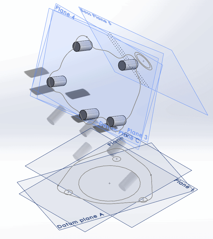
As you can see we are a ways off from a solid model, but we have begun creating the framework necessary to get there.
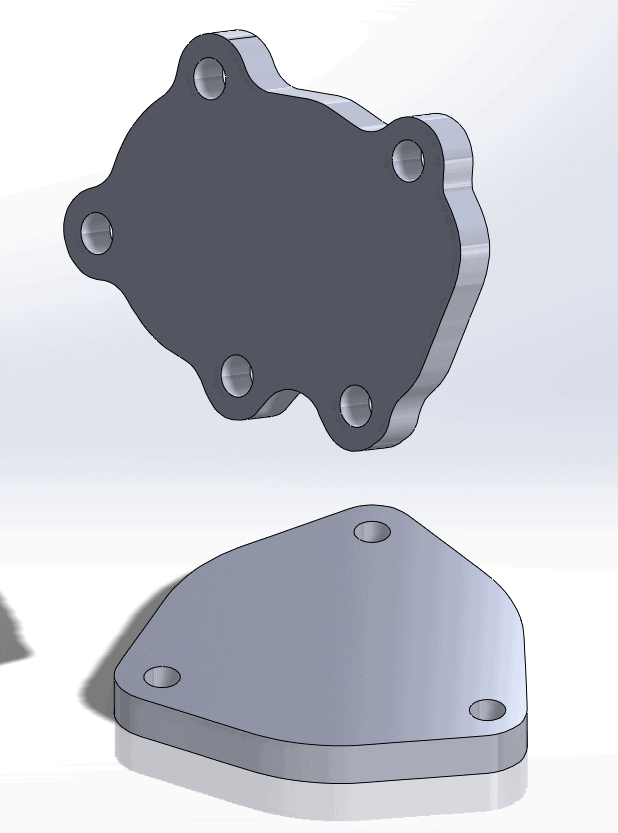
Using basic extruded boss and extruded cut functions, we get our flanges.
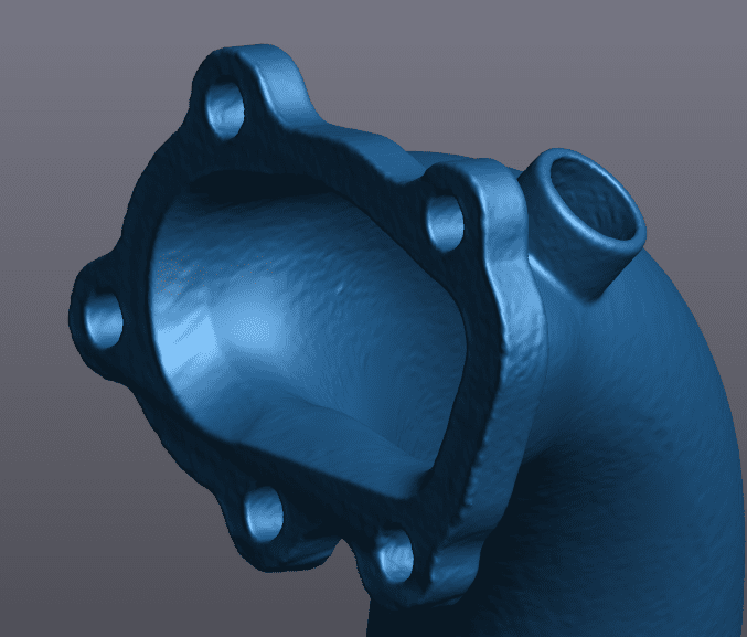
Next, we will head back to our mesh in VXModel to get the inner and outer surface of our pipe.
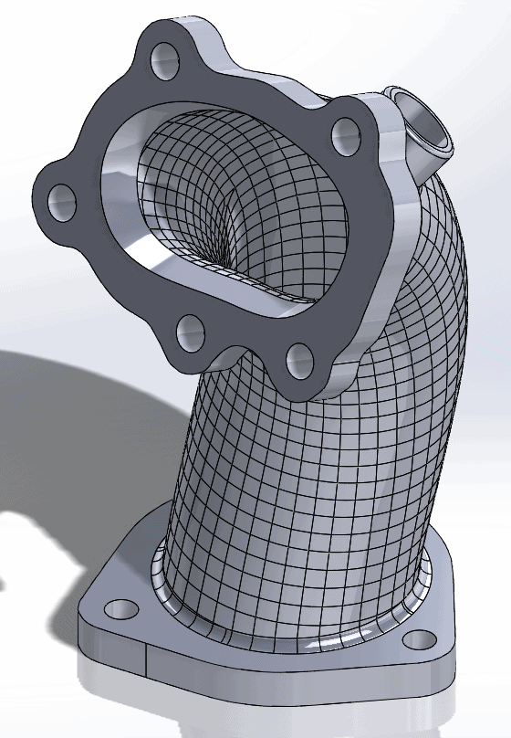
We are going to be using VXModel’s Autosurface function to essentially shrinkwrap our part to capture all of the unique surface curvature present on the pipe. Because it is a full shrinkwrap, it will capture all geometry present in the mesh, which we don’t need as we’ve already created our flanges. So we’ll start off by creating a copy of our mesh, cutting off the flanges and patching over the resultant gaps. After some more mesh cleaning, here is our result.
Now to run the Autosurface function. Depending on the size and complexity of the part this can take anywhere from a few seconds to several minutes.
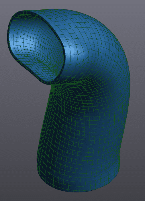
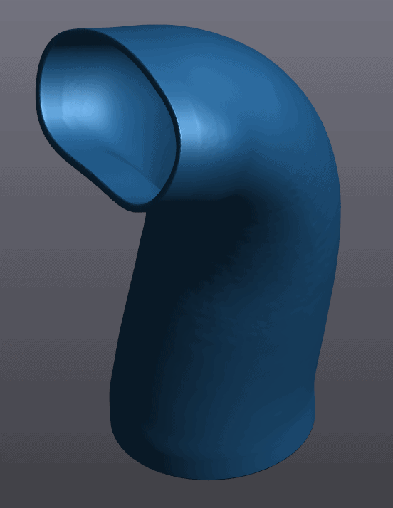
So as you can see, we’ve essentially fit a bunch of CAD surfaces on our mesh to capture that organic curvature as best we can. Transferring this to Solidworks, we retain our orientation to our flanges from before, as our alignment in VXModel is applied to both the original mesh and this flangeless one.
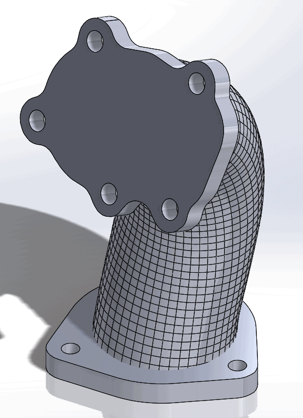
Almost done, the surface body and the two flanges are still separate entities. They need to be combined and the ends of the pipe cut out.
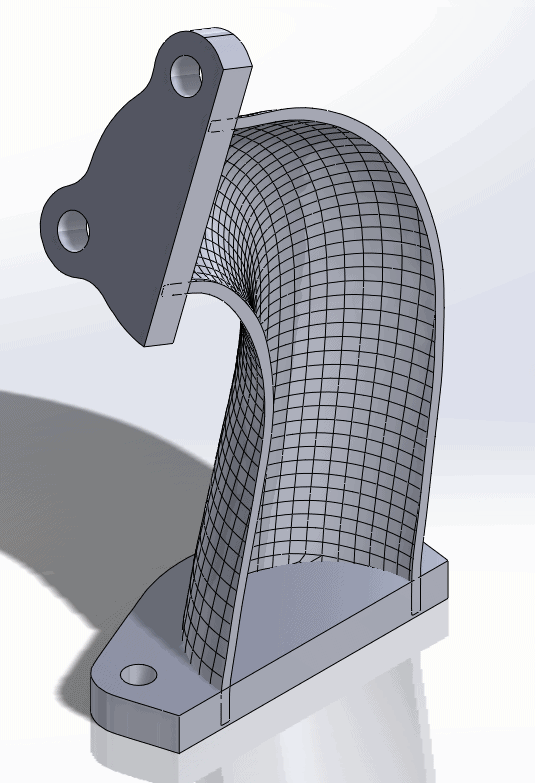
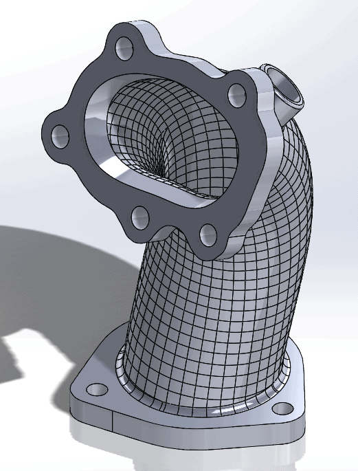
Once we combine the bodies and cut the ends open (and add some fillets for style points) we arrive at our final CAD file.
All in all, this scan to CAD process took about one hour vs the 20 mins for the less involved scan to 3DP process from the last post. A lot more functionality out of the back end for a bit more time investment upfront.
Cullen Williams
Application Engineer
Computer Aided Technology, LLC