Electronic Fit, Function, and Validation: Design to Manufacturing Series (Part 7)
 Spring cleaning has come and gone, yet the clutter persists. In the act of redeeming a missed opportunity for bettering our work environment, the Application Engineering team at Fisher Unitech has sprung into action to create some elbow room, while hard at work servicing manufacturing. An all-in-one wireless charging phone stand and headset holder takes center stage. We recently saw two design possibilities: The Holster and the Transporter, which both have been designed using a variety of tools and functionality within SOLIDWORKS.
In both of these designs, we were able to overcome a few challenges that involved loads, stresses, and tolerances. We used 3D scanning, motion analysis, simulation, and 3D printing, among others to put us back on track. In today’s addition to our Design to Manufacturing Series, we detail the electrical aspects required for the scope of this project and the tools used to assist in our product development efforts.
Part 1 | Part 2 | Part 3 | Part 4 | Part 5 | Part 6
The electrical components
 When working to incorporate wireless charging and lighting into our phone stand designs, we need to consider enclosure constraints and thermal impact of any power-consuming members of the finished product. This brings the phone, LEDs, PCB, and coils into careful consideration.
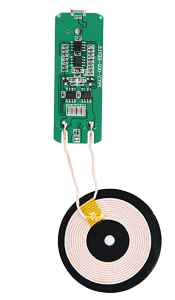
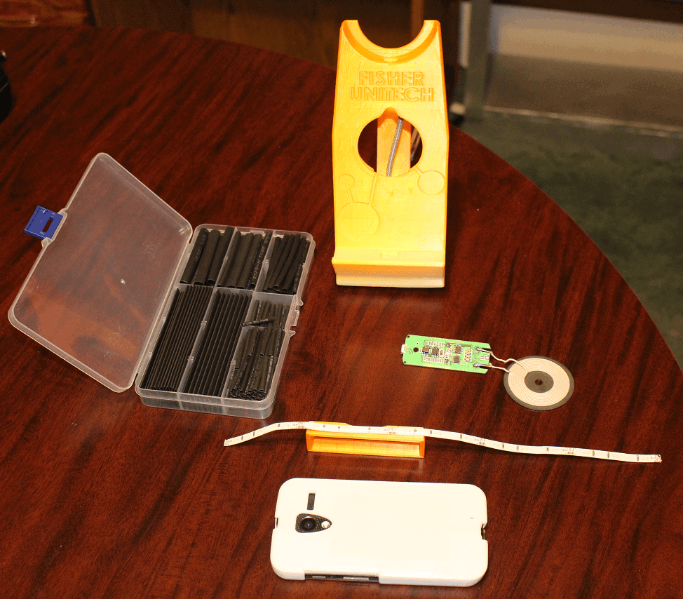
Our first order of business was the selection of components. We chose a PFCY Qi-enabled device based on its favorable balance of size, power rating, price, and efficiency. We also selected some DANCRA LED strip lights based on their ideal length for our prototype stand models, low profile, and side-emitting light.
Achieving precise fit for a PCB
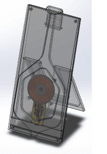
When attempting to reverse engineer our selected board, we have a few options to confirm fit. We could break out the calipers and model a part representing the worst-case scenario for fit; however, since this stand is a decluttering device first, profile is of great importance. To further complicate things, we also have to consider the positioning of our power transmission coil. To get a 75% efficiency or greater in the transmission of power, we need to have our coil within 0.2” of our receiver coil with relatively concentric alignment. With many cell phones today the receiver coil is built into the body of the phone behind a beefy, protective case. These considerations mean we need to represent our printed circuit board and coil accurately in an attempt to model an enclosure with fewer constraints. We certainly could model each component on the board and mate them carefully where they belong, but such a time consuming detailed endeavor begs the question if there is a better way.
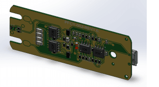
 An introduction to SOLIDWORKS PCB is in order. SOLIDWORKS PCB is a standalone schematic capture and board layout tool that has all your major fabrication outputs available. What makes the use of SOLIDWORKS PCB a great choice in our phone stand project is that we can seamlessly collaborate our design back and forth with SOLIDWORKS. In other words, we can use our library of components to complete our schematics and board layout and use this information to create a SOLIDWORKS assembly that will precisely help us identify our board fit. We even get copper and silkscreen information as a result of this collaboration. Notice a change that needs to be updated in the assembly? No problem, just modify the assembly positioning, and SOLIDWORKS and SOLIDWORKS PCB can be updated.
Now that we can confidently design our phone stand around our board, it is time to validate the material and electronic behavior of the complete assembly during operation.
Thermal validation
To validate how our phone stand will behave or operate over time, let’s take a step back and define our boundary conditions related to power, material, and environment. Our heat-producing components involved are the phone, PCB, coil, and LED lighting. Our final product will be injection molded polycarbonate or PC for short
Our thermal constraints are as follows:
- PC has a glass temperature of 297°F
- Our LED strip has an operation range of 14-105°F
- Some phones can operate “normally” at up to 110°F
Our areas of interest-based on the constraints above are how our LEDs will perform in their environment as well as the behavior of the phone stand’s material.
Our power ratings are as follows:
- The PCB and coil are rated at 10W
- The LED strip is rated at 2W
With our thermal constraints and power ratings defined, we can use SOLIDWORKS FLOW Simulation to review the theoretical performance of our stands.
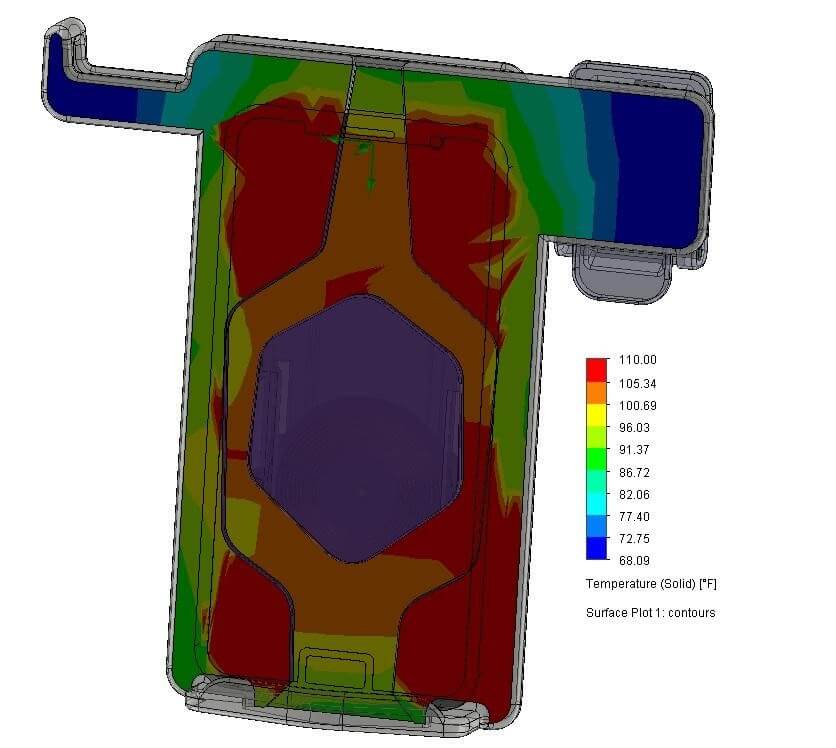
Based on our preliminary analysis, we see that we are reaching steady-state temperatures at over 105°F. We can conclude clearly at this point that our phone stand material will hold up just fine with a glass temperature of 297°F. There is still concern about the performance of the LED strip lighting, however.
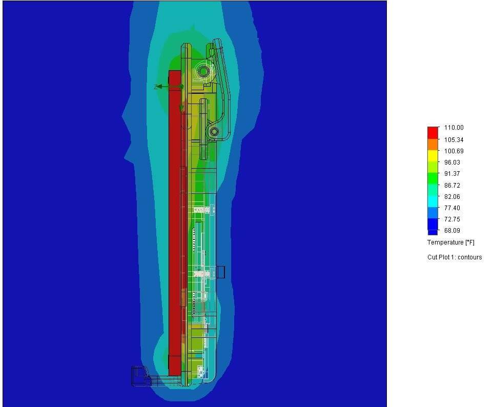
Upon closer inspection, we see that the LED strip location gets up to just shy of 100°F under a worst-case scenario. This appears to be acceptable; however, it is close enough to our upper range of operational temperature that a physical prototype is warranted.
Prototype
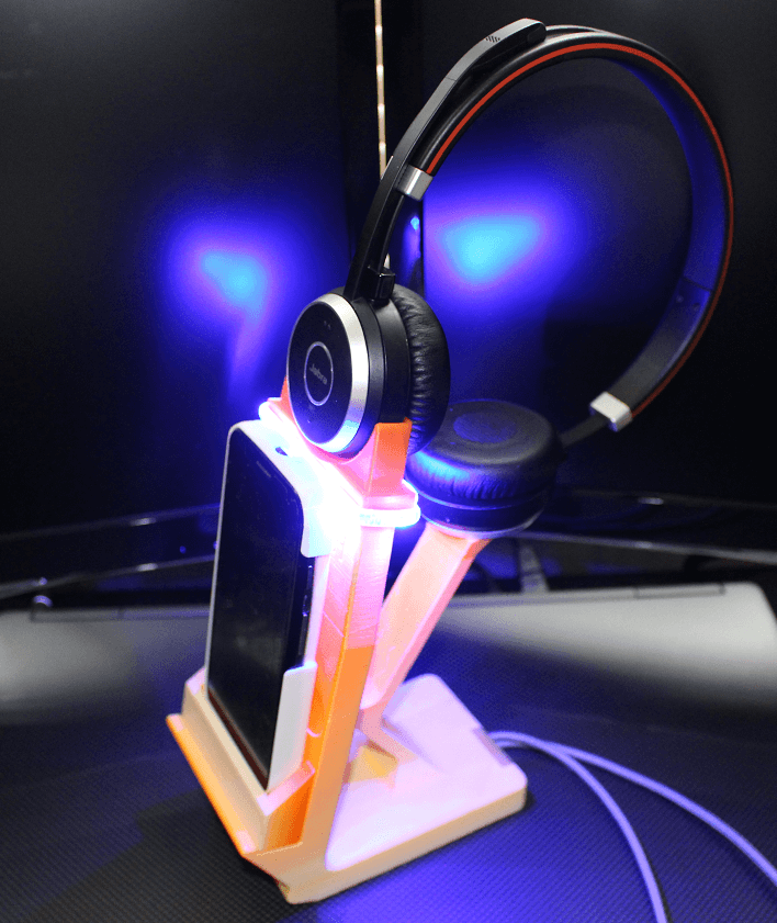
In our prototype build, we will set up a stand that will test for our board fit, phone charging, and heat delivery straight from the worst offender to our LEDs, and why not throw in a logo or two for good measure along the way.
For our test to model, a worst-case scenario for the LEDs, we need to incur as much phone heat as possible. Note: Do not try this at home. We ran our test phone down in power then charged it up while running a few power-hungry apps, all of which was done in an ambient environment of 85°F. Yes, to show our true dedication to our engineering efforts, the office AC was turned off for testing. Barbaric but effective.
The results?
After running this test off and on for a few weeks, there were no noticeable effects on the LED performance due to phone heat. At this point, we are confident in the performance of our phone stand materials and electronic operation in a worst-case scenario, which brings us to the final stretch, a time for the last run of tweaks, prints, and ordering of materials. It’s time to evaluate if our extra elbow room was worth the blood, sweat, and tears as we ponder the next journey to go on from one engineer desk to another.
The next level design
… Speaking of next journeys. This whole process is based on the constraint of a purchased wireless charger. In other words, we had to design around the board, which is often true in industry as well. This begs the question, while there were many boards to choose from, what would be the impact of not being restricted to a specific form? How might our finished product be improved if we had more freedom with the board and even coil shape? Stay tuned as we investigate how a wireless charger phone stand design can be impacted when reversing the constraints to the PCB environment. We will examine this shift in workflow by taking a deeper dive into SOLIDWORKS PCB and the Dragonfly Nano Dimension PCB 3D printer.
Want to see our final design in person? Join us at one of our SOLIDWORKS 2020 Design to Manufacturing Events.
Related Articles
Is it Time to Give Your SOLIDWORKS Skills a Tune-Up?
Get up to Speed with 3DEXPERIENCE
Speed up Selections with these SOLIDWORKS Selection Tools
About the Author
 Mark Talbott is an Application Engineer specializing in SOLIDWORKS Electrical and PCB and is based out of our office in Cleveland, OH. Mark graduated from Grove City College where he received his BS in Electrical Engineering and received his Master’s degree in Electrical Engineering from The University of Akron. Prior to joining Fisher Unitech in 2018, Mark has over eight years of experience in the field helping customers with their Electrical requirements.