SOLIDWORKS Plastics Analysis: Design to Manufacturing Series (Part 9)
 If you’ve been following along with our Design to Manufacturing Series, then you’ve seen the ins and outs of two design concepts for a functional headset and cellphone stand. We narrowed the design down to two concepts, “The Transporter Project” and “The Holster Project”. In our last blog, we discussed some challenges we faced with the Holster Project and brought in SOLIDWORKS Simulation Standard to resolve issues surrounding the spring force. In this blog, we’re going to use SOLIDWORKS Plastics to help us determine how well our project would hold up in mass production.
From personal experience, it’s easy to put a lot of effort into solving a problem only to introduce another. So when I started evaluating the Holster Project early on, I wondered if mass production was a design criterion. The function of the design was great, but how would it be made? It would be easy to produce 3D printed prototypes, but overall, it required some redesign in order to be suitable for mass production. Once the revisions to the design were made I could run the design using SOLIDWORKS Plastics. Let’s take a look at how to run the analysis and results.
Address Concerns Beforehand
When designing plastic parts, I generally have three manufacturing questions:
- Will the part fill?
- Will there be any sink marks?
- How long will it take to cool?
The first two are more obviously critical because if the part doesn’t fill or look good then the design is a failure. (Someone has to pay to modify the mold and that gets noticed quickly). The third can often be more expensive over the long run than the first two.
There are often two competing factors that cause these three issues.
- Thin parts often have minimal sink marks and cool quickly, but are prone to not filling.
- Thick-walled parts fill easily but take a long time to cool and are prone to sink marks.
It’s always possible to get the worst of both worlds as well. Depending on the thickness ratios throughout a part, it’s possible to get parts that don’t fill, take forever to cool, and have large sink marks.
I ran the design through SOLIDWORKS Plastics and within minutes I got my results. I set up the molding condition such that the inner charger housing is an insert in the mold because we wanted to see if the outer housing can be over-molded.
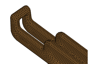 First is to set up the outer mesh. Generally, I like to have three elements across the thickness of any features, it’s a good rule of thumb and usually ensures a fine enough mesh to get reliable results. This rule of thumb tends to keep the aspect ratios of the elements within an acceptable range. SOLIDWORKS Plastics provides a summary of the mesh and can fix most bad elements automatically.
From the outer mesh, the inside mesh can be quickly generated. Materials are assigned for the Cavity (outer housing), the Mold, and for the Insert (inner housing). I set up some Process Parameters which include the injection machine’s clamping force and boundary conditions such as the game location. SOLIDWORKS Plastics can offer suggestions for the gate location or the user can choose to move it. With all of the parameters set, we can run the analysis.
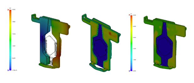
SOLIDWORKS Simulation Plastics Analysis Results
SOLIDWORKS Plastics provides a graphical representation of the results (and a Results Advisor) for the following fields:
- Fill Time
- Cooling Time
- Pressures & Temperatures at the end of the fill and end cooling time
- Sink Marks
- Weld Lines
- Air Traps
I won’t show all of the results available, but the summary of this study is that this part will fill, some areas will have sink marks if additional design tweaks aren’t made, and it will take approximately six seconds to cool.
If we move ahead with this version, our designers know where they will need to focus their efforts to ensure this part comes out looking as good as they imagined the first time the mold is cut. With design iterations taking a matter of hours and costing essentially nothing but an engineer or designers time, this is a much better way to get a great design, than cutting and recutting molds.
Want to see our final design in person? Join us at one of our SOLIDWORKS 2020 Design to Manufacturing Events.

Related Articles
SOLIDWORKS 2020 Embraces 3D Printing and Says Goodbye to STLs
The Top 5 3D CAD Features in SOLIDWORKS 2020
Finding a 3D Printing Services Provider in Michigan
About the Author
 Nathan Sneller is a mechanical engineer, entrepreneur, and adjunct professor. Before joining Fisher Unitech, Nathan graduated from Michigan State University, taught Mechanical Design at Grand Rapids Community College and ran an engineering firm where he specialized in the development of electro-mechanical products. In his current role, Nathan advocates for incorporating simulation software into the design process to shorten the development cycle, improve product performance and maximum profitability.