Programming Threaded Holes in SOLIDWORKS CAM
 SOLIDWORKS CAM is an add-on to SOLIDWORKS CAD that is packed with a variety of features from 2.5 axis milling to 2 axis turning. A frequent question I receive from CAM users is “how do I create a toolpath for a threaded hole in SOLIDWORKS CAM?” There are two methods to accomplish the programming of a threaded hole in SOLIDWORKS CAM: starting with the hold wizard or starting with a simple extrude cut. In this blog, I’ll cover both of those methods. Let’s take a look.
Note: The following tutorial is for learning purposes only. For best results with SOLIDWORKS CAM, users must have an understanding of their machines, machining parameters, and machining concepts.
How to program a tapped hole with the SOLIDWORKS Hole Wizard
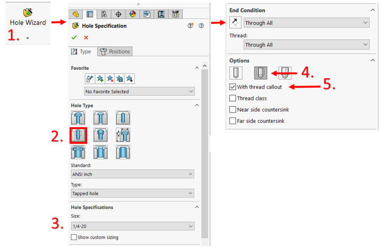
- Click “Hole Wizard” on the Features tab in the Command Manager.
- Select the “Straight Tap” option.
- Select all of the specifications needed for the tapped hole (e.g., size and end condition).
- Scroll down to the bottom of the Hole Wizard Property Manager to make sure “Cosmetic Thread” is selected.
- Make sure the “With Thread Callout” option is checked otherwise the tap program in SOLIDWORKS CAM will not function.
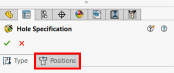
- Once the hole specifications are selected, choose the “Positions” tab at the top of the Hole Wizard property manager.
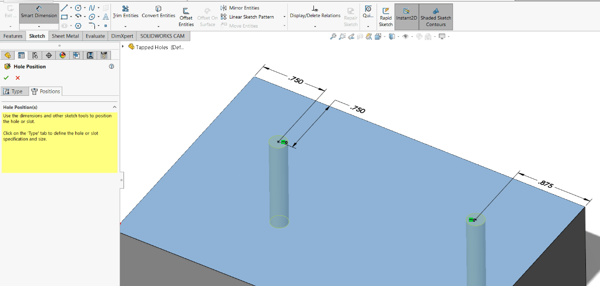
- Choose a face to place the tapped hole on.
- Click to place a hole or multiple holes.
- Hit “Escape” on your keyboard to stop adding holes.
- The Hole Wizard tool is still active: choose “Smart Dimensions” to place dimensions on the center point of the new holes to position them. Relations can also be used.
- Click the green check to complete the command.
- Choose “Extract Machineable Features” from the SOLIDWORKS CAM tab.
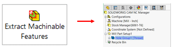
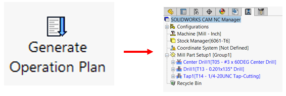
- Choose “Generate Operation Plan”.
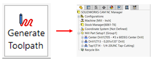
- Choose “Generate Toolpath”.
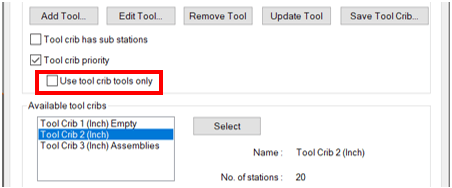
Tip: If you set your Toolcrib to “Use toolcrib tools only”, SOLIDWORKS CAM will not search outside of the specified Toolcrib to grab the correct tap cutter and drill for the minor diameter. If that’s what you intend, select that option, otherwise leave it blank so that SOLIDWORKS CAM can search the entire TechDB for the appropriate tap and a drill for the minor diameter.
Program a tapped hole with a simple extrude cut
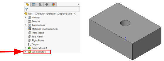
Notice that the hole found in the screenshot below was created using an extrude cut feature. This example shows a hole that is ¼” in diameter and the end condition of the cut is Through All.
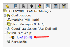
- Click “Extract Machinable Features”. SOLIDWORKS CAM will choose Drill as the Strategy because the feature is just seen as a hole.
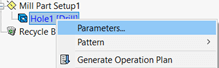
In order for SOLIDWORKS CAM to program this hole as a threaded hole, the strategy must be changed. - Right-click on the Hole1 Feature in the SOLIDWORKS CAM Feature Tree.
- Choose Parameters… to open the Hole Parameters Dialogue box.
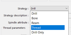
- Choose the “Thread Strategy” from the drop-down menu.
- In the Hole Parameters Dialogue box, users can also set the Threading Method:
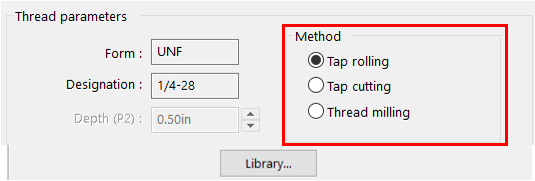
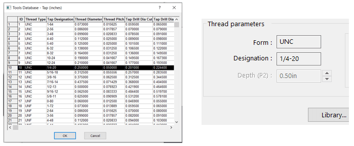
Right now, the thread is set to ¼-28, but let’s say I want to use a ¼-20 thread. I need to change the thread to ¼-20. - Click “Library…”
- Choose the appropriate thread type and click OK then click OK again to exit out of Hole Parameters.
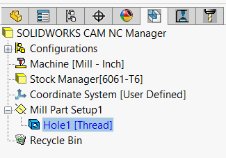
Now the hole strategy in the SOLIDWORKS CAM Feature Tree should say Thread:
- Choose “Generate Operation Plan”.
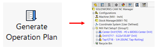
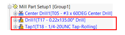
Note: Any operation that has a tool warning icon in front of it means that SOLIDWORKS CAM had to go outside of the specified toolcrib (into the Technology Database) to get the appropriate tool. In my example, I did not have the appropriate tap or drill for the minor diameter of the hole in my specified toolcrib so SOLIDWORKS CAM went into the Technology Database to get them.
- Choose “Generate Toolpath”.
The hole is now seen by SOLIDWORKS CAM as a threaded hole. For more SOLIDWORKS CAM tutorials subscribe to our blog. See you all next time.
Related Articles
The Difference Between SOLIDWORKS CAM Software: CAM Standard Versus CAM Professional
How to Customize Tools and Tool Cribs in SOLIDWORKS CAM
Using SOLIDWORKS CAM and CAMWorks
About the Author
 Amanda Osbun is a Support Engineer at Fisher Unitech. She graduated from Millersville University with a Bachelor of Science in Technology and Engineering Education. As a BSE in Tech Ed, Osbun has worked with SOLIDWORKS and CAM since college and has continued this interest in working with designers and engineers to help them better understand the software that makes so many things possible.