Design Intent: Part II
This is a continuation of Design Intent: Part I, which you can read by clicking this link here: The order in which these can be read does not particularly matter.
In Part I, we used the geometry of a STEP file to create weldment bodies to match our design intent and communicate meaningful information downstream.
In Part II, we will look at SOLIDWORKS Automatic Feature Recognition (AFR) tool. SOLIDWORKS possesses the ability to translate neutral file formats, or “dumb” solids into fully modifiable features for us. Dumb solids include anything that translates into SOLIDWORKS feature tree as an “imported solid.” Most often these are STEP files but can be IGES, Parasolid, or other file types. Although their geometry is 3D, CAD will only allow minimal design changes to a dumb solid. We can perform commands like Move Face to change the size or length of a component, or add holes to a part, including from within the context of an assembly.
So, before you attempt AFR, ask yourself, “What might I need to change in this part? Do I only need it to show up in a BOM correctly? Am I mounting this somewhere and need to be able to place the mounting holes? Is this being outsourced?” If you’ve answered yes to any of these questions then you might not even need to worry about converting your legacy data into a part for full revision control.
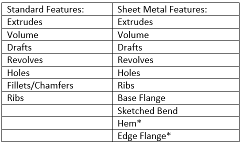
Detailed list of features that SOLIDWORKS can interpret. * indicates only some conditions can be interpreted. Click here for more information.
Now that I’ve covered when you shouldn’t consider SOLIDWORKS AFR, let’s talk about when you should consider it. Although Automatic Feature Recognition is an advanced and convenient tool, it cannot replace our design and engineering mind. That being said, there are limitations that come with utilizing it, especially when it comes to considering design intent. Creating a 3D model with a specific strategy in mind so that modifications to the model are easily and properly rebuilt is known as “design intent”.
This is important to keep in mind when utilizing AFR. SOLIDWORKS can interpret parts into both standard features and sheet metal features but doesn’t always translate it into features we would expect. See Table 1 for a list of features that SOLIDWORKS can try to interpret.
Standard Features: SOLIDWORKS does best with basic parts. It can interpret geometry with consistent cross-sections through linear extrusions or across infinitely many planes like a revolve. While considering design intent, ask yourself, “would this STEP file be created using either Extrude or Revolve?” If neither, SOLIDWORKS might not do a good job interpreting everything. If you’ve said yes to one or both these questions, you then need to consider design intent. “Is my design intent to have a revolved sketch or a linearly extruded sketch?” To best explain this, I’ve created a simple bolt for SOLIDWORKS to interpret through AFR.
Before beginning Automatic Feature Recognition, turn off 3D Interconnect by going to Tools>> Options>> Import and toggling the checkbox OFF. After turning this off and opening the neutral file, 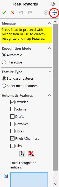 SOLIDWORKS will attempt to repair the faces and automatically ask to recognize features. You can also access by going to Insert>> FeatureWorks>> Recognize Features. You’ll have a few options here, but for brevity, we’ll stick to only discussing “Automatic” recognition.
We then select how we want SOLIDWORKS to interpret the data. In most cases here, less is more. Only precise features that you would expect to be in the model should be selected. Let’s see what happens with Extrudes and Fillets selected. The box for “Local recognition entities” may be selected if you want to only have partial revision control over some entities. (This is a great method for utilizing a Hybrid modeling approach and can help partially interpret neutral files to be just enough for partial revision control). We can click Next, circled in red. Here, it will show you what SOLIDWORKS recognized, and we have the option to try to combine features or re-recognize them as different features, a useful tool.
Now, let’s see how SOLIDWORKS interprets this model…
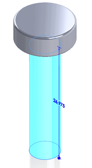
SOLIDWORKS creates two circular sketches, extruded them to size, and added two extra fillet features into the Feature Tree for a total of 4 features. This could be useful if I wanted to suppress fillets in different configurations, but for the most part, it doesn’t give me much strategic control as it relates to design intent. Let’s revert to our backed-up STEP file and try using revolve, instead.
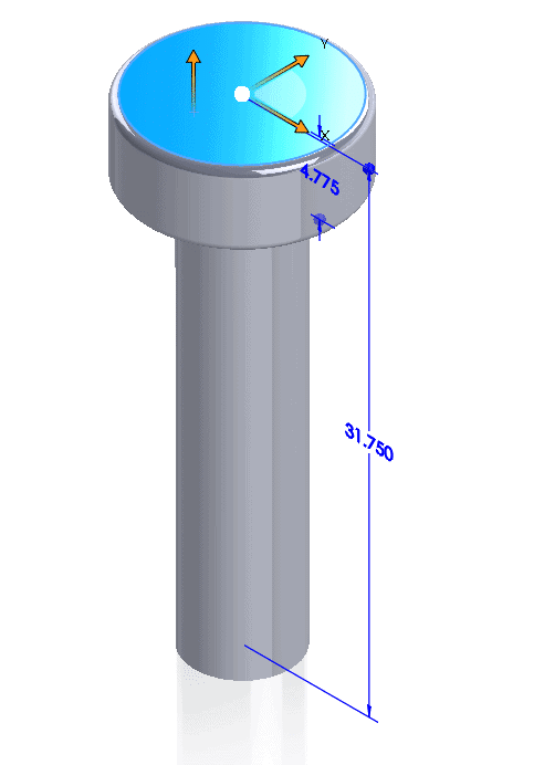
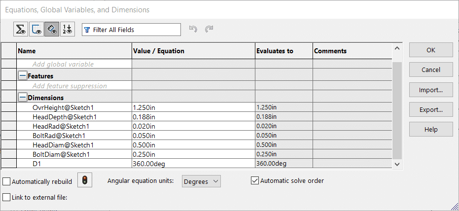
We’ll only select “Revolve” in AFR. Fillets can be built inside of a sketch, but also as features. This choice is given by the 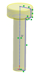 Automatic Feature check boxes. In this case, I want the fillets to be included in a sketch, and fully controlled within one feature. When we choose to only use Revolve, we get one single sketch with fillets. We will dimension this and give names to each dimension to match its design intent. An easy way to give names to dimensions is to access Tools>> Equations and click on “Dimension View” at the top left.
Lastly, we can use a design table to control these dimensions and create a whole library of configurations with just one translated sketch! Now, that’s design intent at work!
If you are an individual reading this and disappointed that their file(s) are not being translated, be sure to reach out to our great salespeople and ask about Elysium, a CATI Partner Product, for better, fuller revision control software that can help you bridge the gap between your previous CAD software and SOLIDWORKS. Through CADFeature, Elysium allows you to capture features, assembly relationships, associated drawings, and other non-graphic properties of the complete model without the manual re-association.
This concludes the second and final part of Design Intent: Utilizing File Translations to Manage Legacy Data. I hope this helps you understand how to not only use the SOLIDWORKS Automatic Feature Recognition tool but use it wisely in a manner that favors your design intent. Happy designing!
Jordan Kleinschmidt
Application Engineer, CSWP
Computer Aided Technology, LLC