Combining Displacement Maps in SOLIDWORKS to Create Natural & Organic Geometry
In the last blog post we discussed creating displacement maps to make customized 3D textures in SOLIDWORKS. In this continuation, we will discuss mixing displacement maps from real life with your own to create more custom geometry. To get caught up on how to apply 3D textures check out the first blog post in this series. To get caught up learning how to create displacement maps check out the previous blog post in this series.
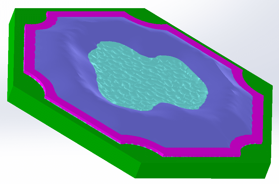
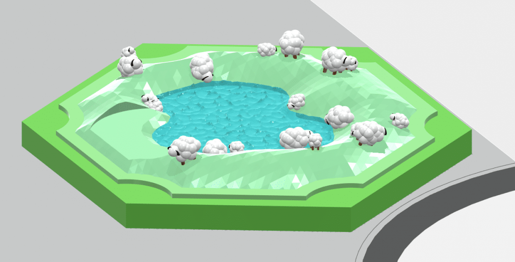
As with previous blog posts, we will be using The Settlers of Catan for inspiration in using our 3D textures. This week will cover the creation of a “wool” piece with sheep on a lake, shown digitally below.
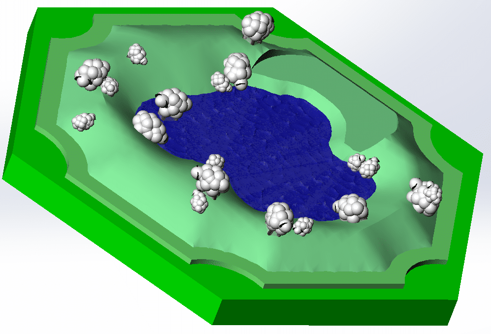
This piece combines a realistic water texture with a hand-drawn circular hill texture. The process is very similar to the “clay” pieces created last time, but with an added layer of complexity.
To start, find a realistic water texture (or whatever realistic texture you desire). There are a few search terms that can be used, including:
- Displacement map
- Height map
- Bump map
- Texture map
An important factor to keep in mind is whether your image is a “seamless” image. Here is a side-by-side of a tiled image (left) and a tiled seamless image (right).
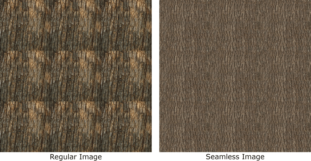
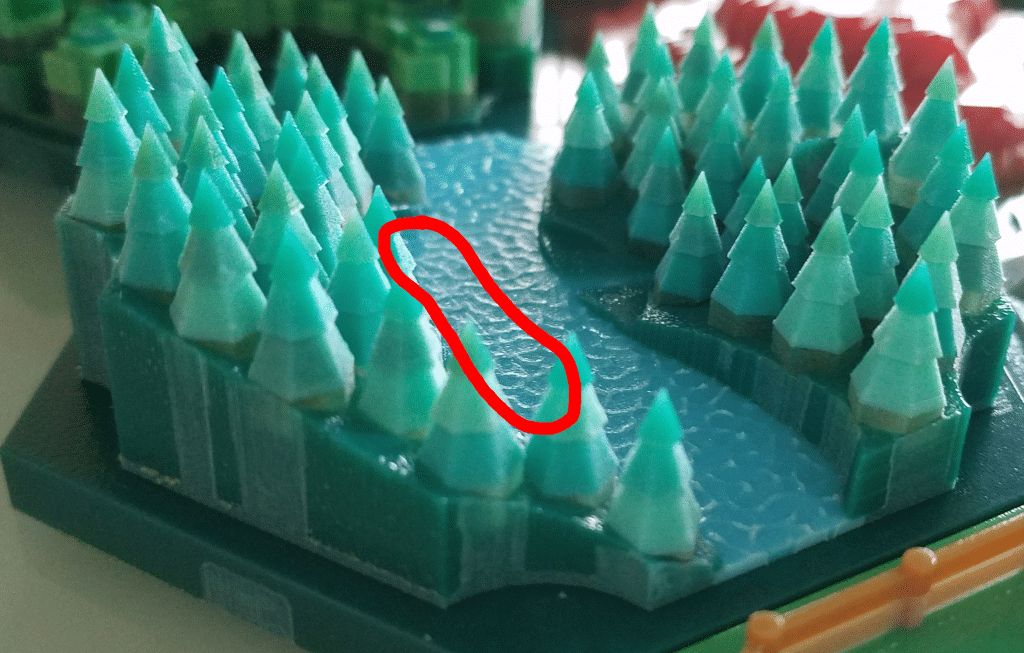
A seamless image will be “seamless” when tiled against itself. That doesn’t mean the seamless image is perfect by any means. The seamless image above has a dark spot that shows up in each repeat of the image, which can ruin the illusion of the seamless image. This is all important to know because SOLIDWORKS will tile texture images. If a regular image is chosen for a life-like texture, the seams of the image become very visible. In the example below, a displacement map of water is being applied to the piece. The image below shows a piece that was created without a seamless water texture.
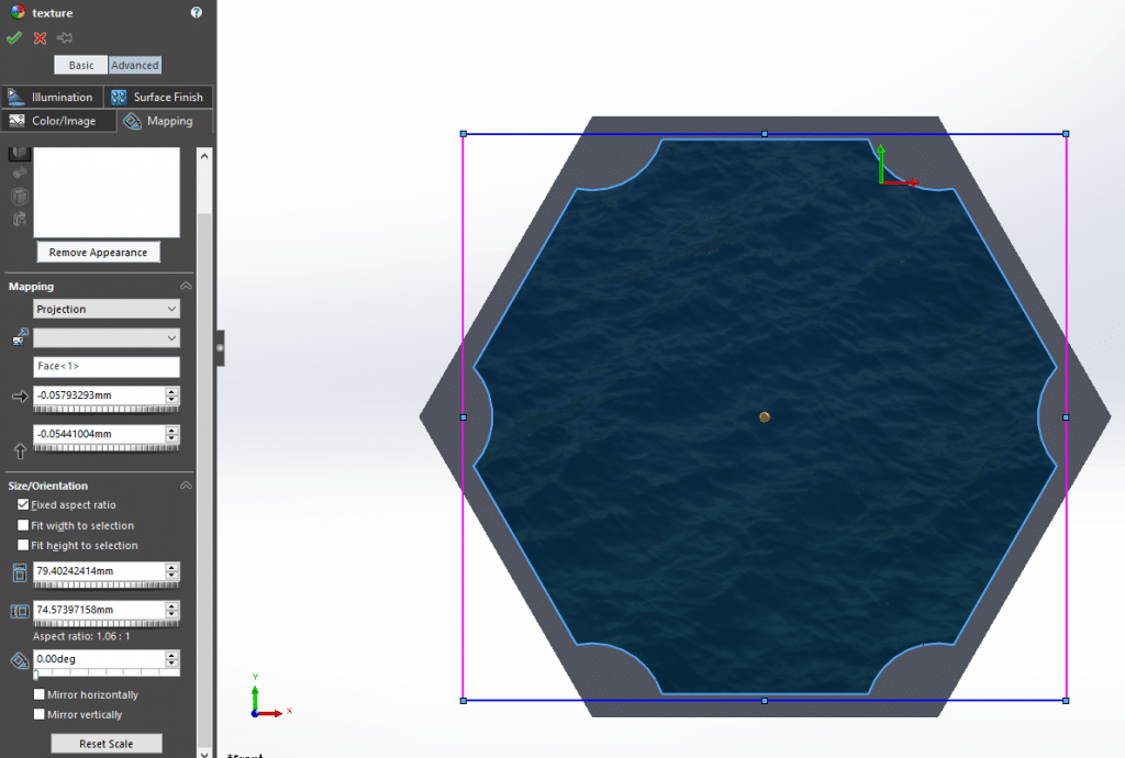
If the texture image chosen is large enough that the image doesn’t tile, the image won’t need to be seamless. In SOLIDWORKS, the size of the image applied as a texture is noted in this pink-blue box created in the “texture” property manager.
With all that in mind, including the word “seamless” in the search or restricting the search to larger files should prevent any poor tiling behavior in SOLIDWORKS.
To start the wool piece, the hill texture was added to the part. This texture was created in GIMP and is shown below. The process of creating these is outlined in the previous blog post.

Below are the settings used in the “3D Textures” feature.
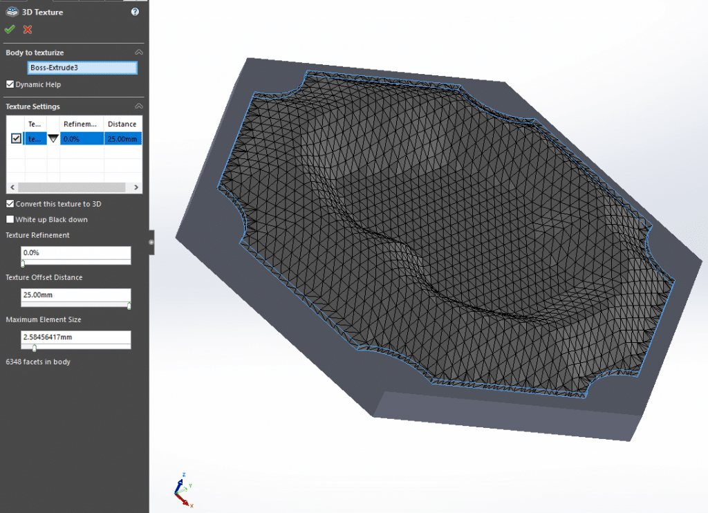
Once applied, the hill was converted from a 3D graphic into a mesh.
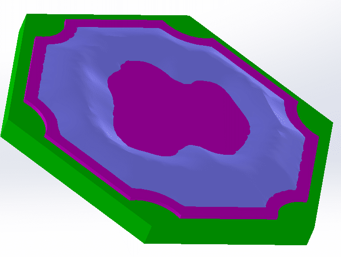
The next step was separating the hill geometry from the base geometry. This makes the hill a separate body, which allows for coloring the hill differently from the rest of the part. The split is highlighted in the image below.
With this split, now the lake texture can be applied. However, applying the water texture to the top face of the pink section would result in the water texture being applied to the entire top face of the pink section. To restrict the water texture being applied to just the center of the piece, another splitting operation needs to be done to split the pink section. To do this, an extrusion that overlaps the inner lake portion was created, shown below.
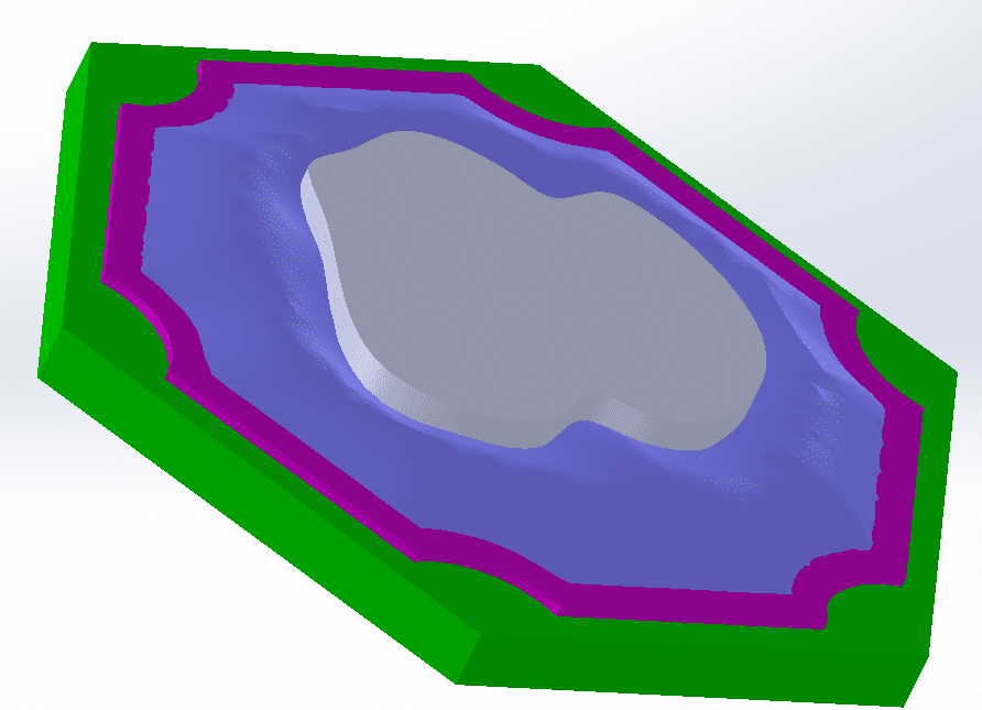
Using the “Intersection” feature, a separate body was created, colored teal-green in the image below.
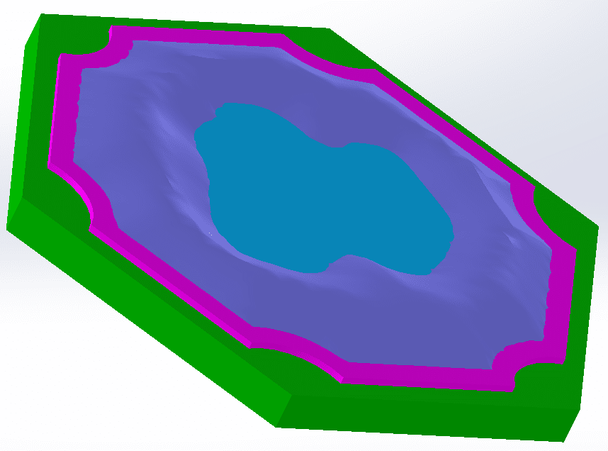
Now the water texture can be applied to the inner teal portion! With the water texture, setting the “3D Texture” settings to the smallest sized elements will make the texture highly detailed. Applying the texture results in the following image.
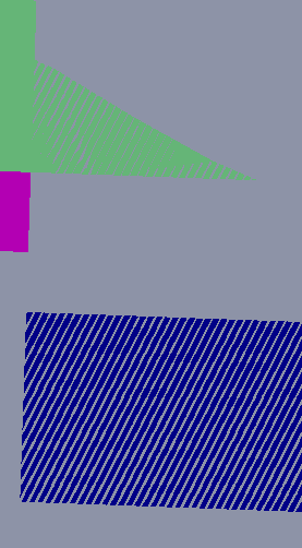
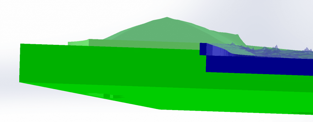
The last step (before adding lots of sheep) is to make another solid body underneath the lake portion. Since the lake portion is going to be colored slightly transparent, having a solid body underneath that is a matching blue color will prevent the green from the base showing underneath the lake. This is a very similar process to the creation of the separate lake body from earlier. One thing to keep in mind while doing this is overlapping bodies. When bodies overlap in SOLIDWORKS, the appearance will become a combination of the two bodies. An example of overlapping bodies is shown below.
To prevent this, use the subtract operation of the “Combine” feature to Boolean remove portion of the overlapping bodies.
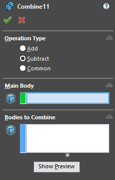
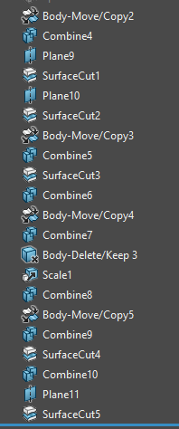
It’s good to note that when using the subtract operation, the bodies in the “Bodies to Combine” section get consumed by the operation. To prevent losing the body, use the “Move/Copy Bodies” feature to copy the body before combining the body. Cuts can also be made using the “Surface Cut” feature using planes. For this wool piece, there were several of these operations used to get to the final piece.
The section view of the final piece is shown below.
Some very simple sheep were created in SOLIDWORKS and inserted into an assembly with the part.
From here, the assembly needs to be transferred into GrabCAD Print. In previous blog posts, SLDPRT and VRML file types were covered, so in this one we will use the 3MF file type. The 3MF file type was recently added to GrabCAD Print’s list of accepted files. This file type allows for separate solid bodies as well as textures to be saved with the part. To do this, make sure to edit the SOLIDWORKS options for the file. From the “Save as” menu, select .3MF file and click on the “Options” box.
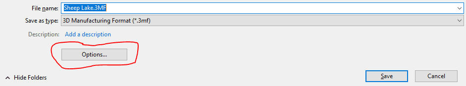
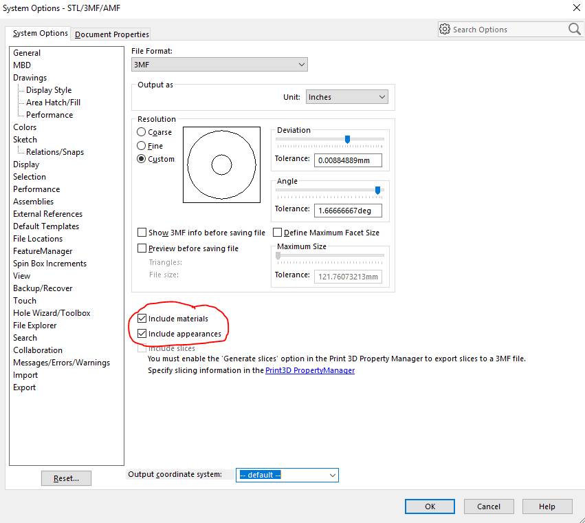
From here, the screen looks suspiciously like changing the options on an STL file. This is because 3MF files were developed to keep the advantages of STLs, but include the advances that had been made in the last 30 years. Make sure to select “Include appearances” (I also selected “include materials” for fun).
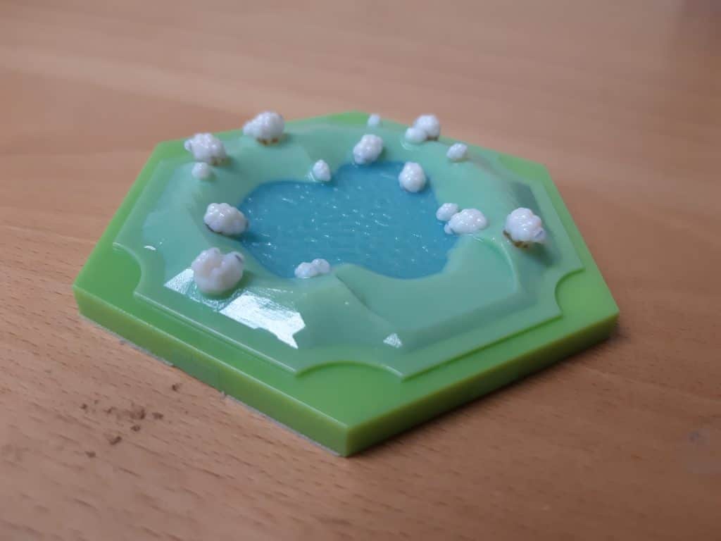
Once saved, the model was imported into GrabCAD Print. Once the proper colors and transparencies were applied, this was the digital result.
After printing and a rinse here are the results!
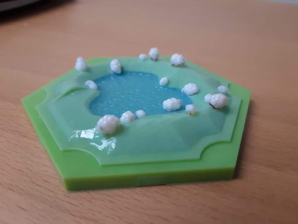
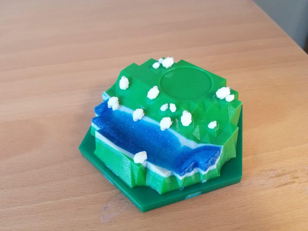
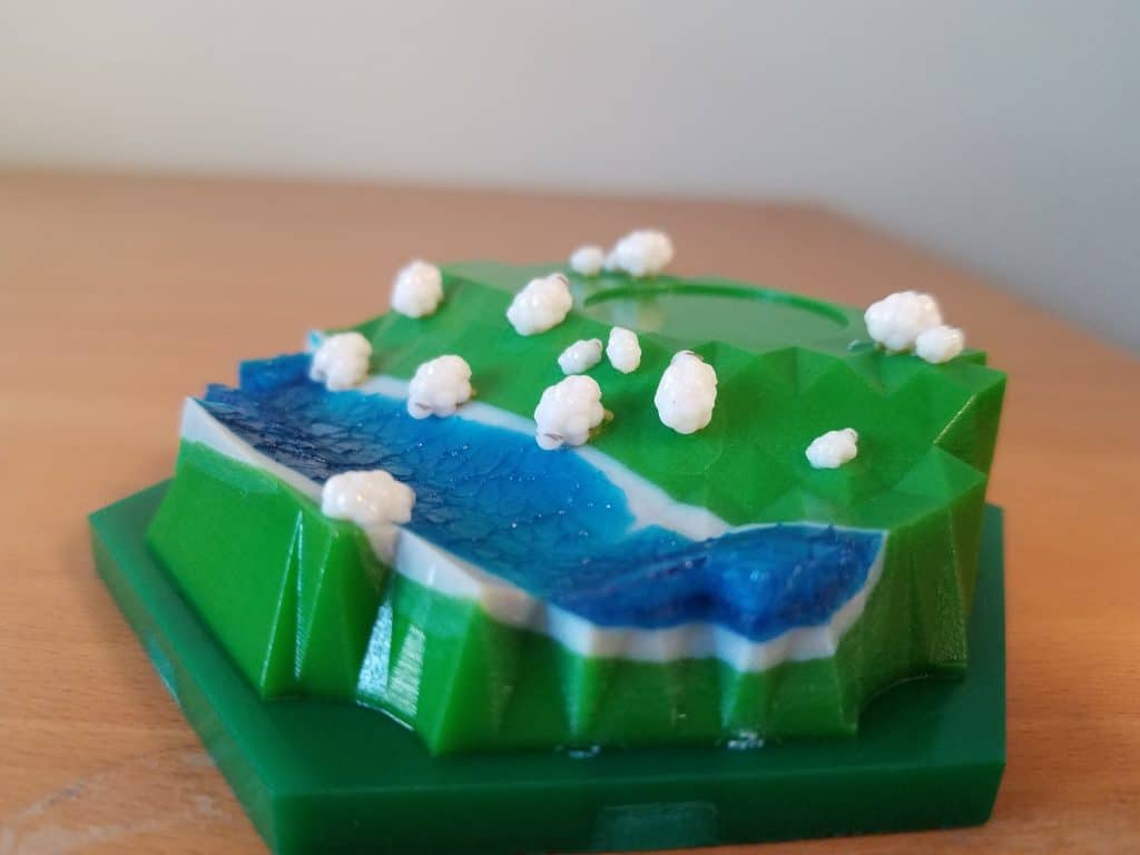
The transparent water with the solid blue backing is very visible in the final product! Combining the realistic displacement map with the custom drawn displacement map opens up many more possibilities to create geometries that would otherwise be unobtainable in SOLIDWORKS. Below is another example
I hope these blogs have helped understand how 3D textures are interpreted in SOLIDWORKS and how easy and useful creating your own texture to bring in more organic geometry. If you have questions about the process or want to see more please reach out!
Until next time!
Kelsey Gabel
Application Engineer, Manufacturing Solutions
Computer Aided Technology, Inc