Creating a new Thread Profile in SOLIDWORKS
 SOLIDWORKS users have been able to enjoy the ease of making threads ever since the release of Thread Profiles in SOLIDWORKS 2017. There are several pre-made types and sizes of thread profiles available, including Die, Tap, and Bottle Threads, as well as multiple different sizes available in each selection. However, there may come a time when you would like to add custom shapes and sizes. In this SOLIDWORKS tutorial, I’ll show you an example of using an existing Bottle Thread Profile to create a Custom Thread based on a 4mm pitch as well as how to configure for additional sizes. Let’s get started.
One of the easiest ways to create a new Thread Profile in SOLIDWORKS is to work with a pre-existing Thread Profile and modify it to your needs. Currently, Thread Profiles are Read-Only files, so you can’t modify the existing file and save. By following the SOLIDWORKS tutorial below, you can create and save the Profile that fits your requirements.
Here are some of the steps we’ll cover to create a new Thread Profile in SOLIDWORKS.
- Verify where your Thread Profile resides
- Edit sketch
- Change configuration information
- Create configurations
- Test the thread profile
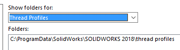
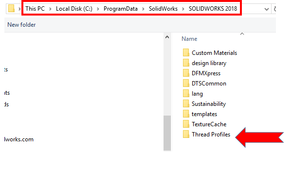
To start, verify where your Thread Profiles currently reside. By default, they are located in C:ProgramDataSOLIDWORKSSOLIDWORKS 201XThread Profiles. (Note: The year should match the current year of SOLIDWORKS you are running.) You can also check the location in SOLIDWORKS by selecting Tools > Options > System Options > File Locations. In the dropdown select Thread Profiles.
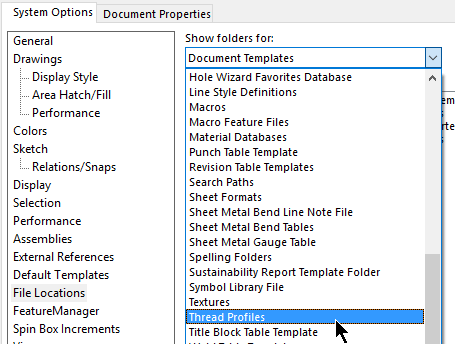
Make a note of the path you find (Note: There is only one location allowed.)
Here’s how to modify a file to make a new Thread Profile in SOLIDWORKS.
Go to File > Open
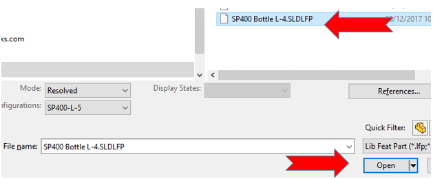
Change File Type to Lib Feat Part (*.lfp,*sldlfp).
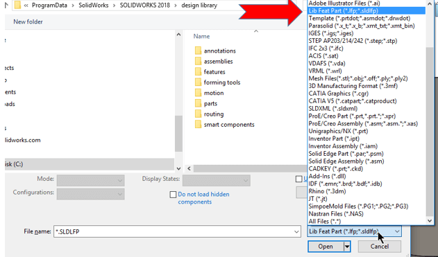
If you don’t see Thread Profiles, click on the folder path window and browse in Windows Explorer for the Thread Profile folder path you found in SOLIDWORKS. Again, the default location is C:ProgramDataSOLIDWORKSSOLIDWORKS 201XThread Profiles.
Select the file you are going to use to create a new profile and open. You will receive a notification that you are opening a Read-Only file.
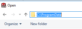
By default, C:ProgramData is a hidden folder in Windows. If you are unable to browse that folder, you can manually type it in at the top of the window and hit enter. Continue to browse to SOLIDWORKSSOLIDWORKS 201XThread Profiles.
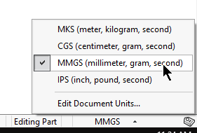
Once the file is open, adjust Unit of Measure if needed, located on the bottom right of your screen in SOLIDWORKS.
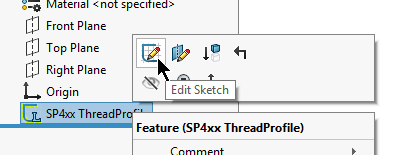
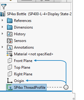
Edit Sketch – (Note: The “L” on the sketch symbol means that it is defined as a Library Feature.)
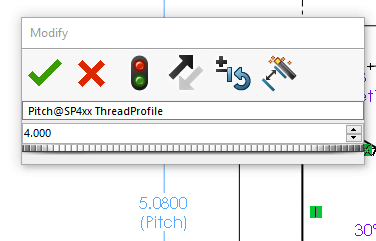
Change dimension(s) as needed – Click OK (green check mark.)
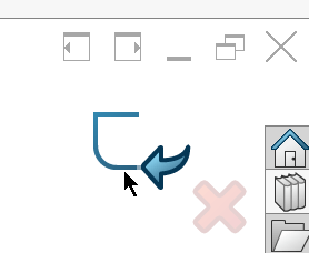
Chose sketch using Confirmation Corner (upper right of the graphics area.)
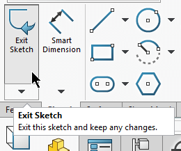
Or, Exit Sketch from the Command Manager.
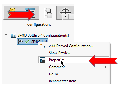
Change Configuration information (third Tab > Configurations >Right-click> Properties) to match your information.
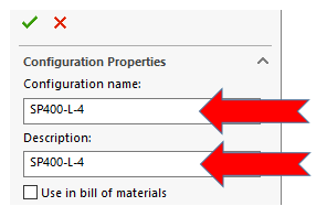
Change configuration name and description then OK (green check mark.)
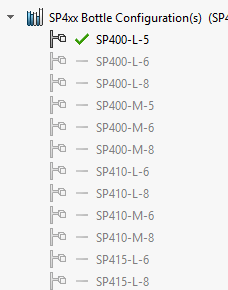
(Note: The original file may come with some additional configurations.)
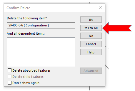
You may choose to delete the additional configurations (click the first grey configurations > hold shift > click last configuration). Right-click and select Delete or hit Delete on your keyboard. You will receive a warning that you are making changes to a read-only document. Click OK.
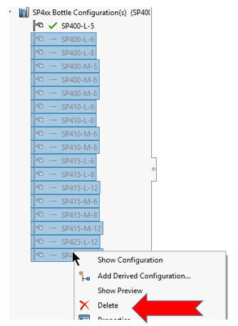
When the window pops up – Select Yes to All.
It’s simple to create configurations with Configure Dimension. Double-click the sketch in the Feature Tree which will show all the dimension of the sketch in the graphics area.
Right-click a dimension (in this example “Pitch”) and choose Configure Dimension.
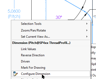
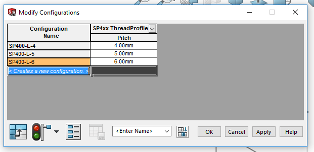
Modify Configurations will then pop up.
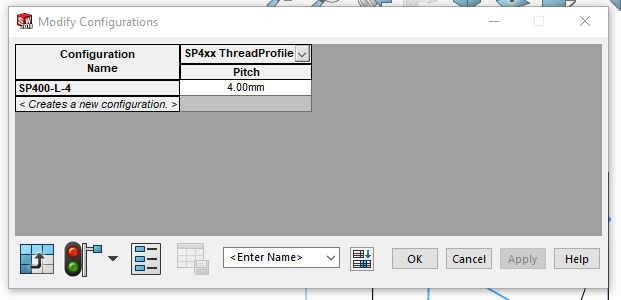
You can now add new Configuration Names and new Pitch Dimensions by typing in the Configuration Name and new Pitch Dimension.
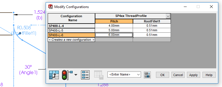
If you want to add a new Dimension to Configure, double-click the Dimension from the graphics area, and Modify Dimensions as needed. In this example, the RootFillet1 was added – when done Click OK.
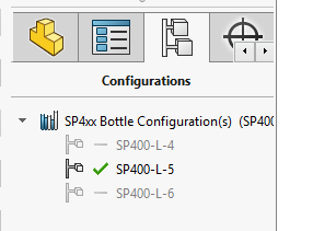
To see your new Configurations, click on the Configuration Tab. You can double-click each of the Configurations to make them active and see the changes in the sketch.
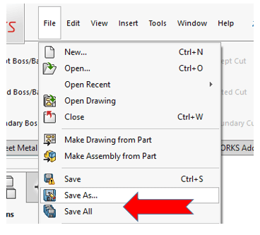
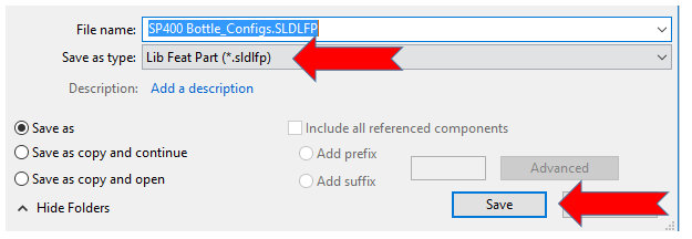
Now it is time to save the file. To save as a new file, go to File > Save As.
Enter in your new file name. You’ll notice that your file automatically saves as an .SLDLFP file (Lib Feat Part). Click Save.
Note: You cannot overwrite existing files, so you have to give it a different file name.
Close your file.
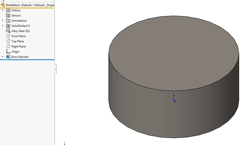
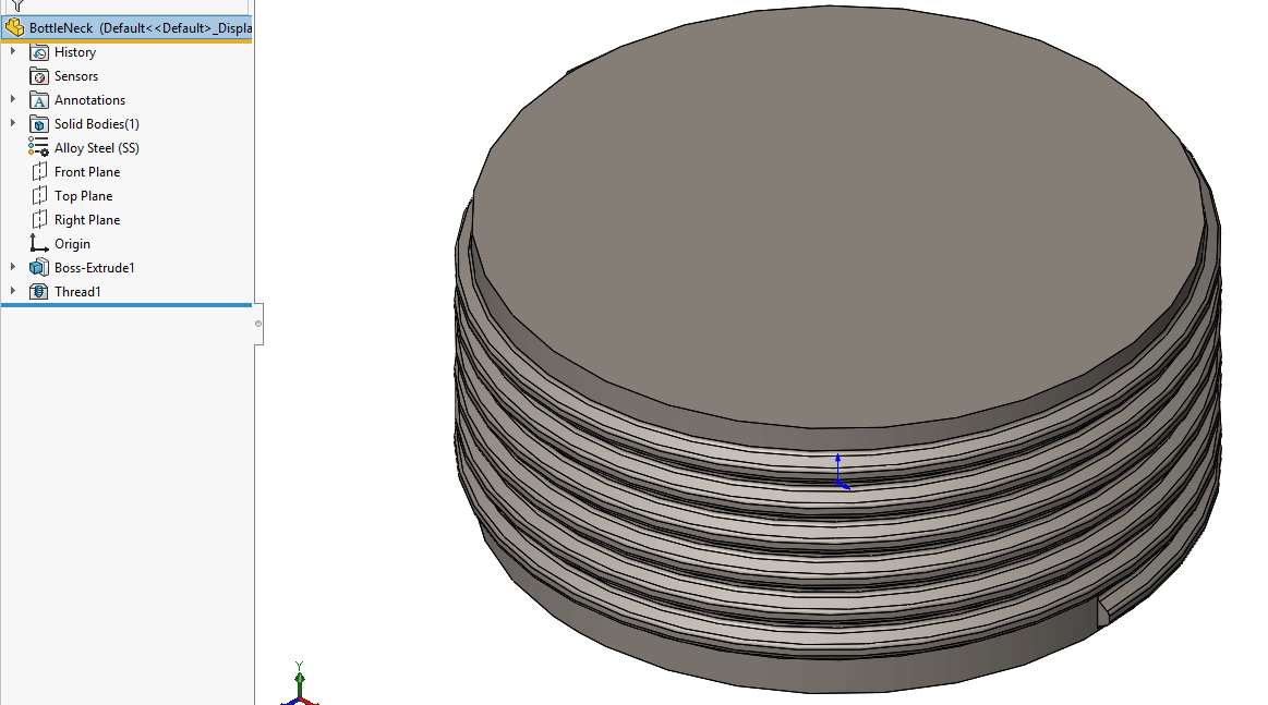
Now it’s time to test the Thread Profile. In my example, the part is simulating the neck of a bottle.
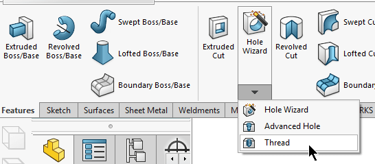
Go to Features > Hole Wizard > Thread.
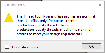
You will receive a message that the Thread tool Types and Sizes are nominal, and if you are looking for Production quality threads, you need to modify the profiles to meet design needs – Click OK.
Define Thread Location or Starting Location: In my example, the top edge of the neck is selected.
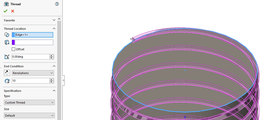
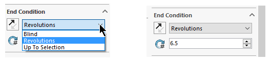
Define End Condition (Revolutions, Blind, or Up to Selection.) My example uses Revolutions.
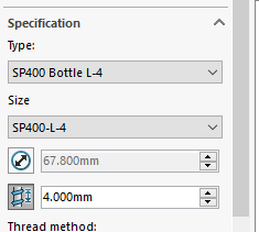
Under Specifications, use the dropdown to change the Type to the newly created file and Size. (If you have more than one Configuration).
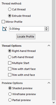
For my example, I’ll change Thread Method to Extruded Thread and define additional parameters such as right or left handed thread or trimming options (use the “?” symbol at the top of the Thread properties to get more information on all the options available when using Thread Profile).
Hit OK and you’re done! Here is the result!
I hope this gives you a great foundation when creating your own custom Thread Profiles in SOLIDWORKS. You’ll soon find how quick and easy it is to use the full power of the Thread tool.
For more SOLIDWORKS Tips and Tricks, be sure to subscribe!
More SOLIDWORKS Tips & Tricks
Beginner’s Guide to Using SOLIDWORKS PDM
SOLIDWORKS Simulation Tutorial: Applying Non-Uniform Pressure
How to Create a Plane in SOLIDWORKS
About the Author
 Cami L. Florence has over 20 years of experience with SOLIDWORKS, design, presales, support, and training; specializing in weldments, sheet metal, and surfacing. She is currently a SOLIDWORKS Technical Support Manager based out of Milwaukee, Wisconsin and has been with Fisher Unitech for over ten years. Cami has presented at SOLIDWORKS World numerous times and is well known in the SOLIDWORKS community for her knowledge-base and passion for helping other users succeed.