Custom Packaging Design (Part 1 of 2)
Recently I was asked to deliver onsite customized classroom training to one of our customers. This meant transporting our entire training lab, containing 10 ea BOXX workstations, 22” Dell LCD monitors, keyboards, and mice, from our office, 181 miles to the customer site. Since we didn’t have the individual packaging for the workstations and monitors, and the cost of commercial custom packaging was prohibitive, I needed to create custom packaging. This meant acquiring crates that could hold all the equipment safely and securely and still be manageable for one individual.
We already had a clamshell container that I thought would be good for most of the monitors, but the rest of the lab required something more sturdy and maneuverable. Before I could purchase a crate, I needed to determine how much space would be required. This was a perfect job for SOLIDWORKS. After modeling the approximate size of each piece of equipment I created an assembly to rearrange and employ patterns to find the most efficient groupings. As well as allow for at least one inch of foam padding around and in between. Then I shopped for a crate with the approximate volume and maneuverability to accommodate the equipment that wouldn’t fit in the clamshell crate. I modeled the clamshell crate, by measuring the actual crate and added it to an assembly. I then added as many of the monitors (8), 2 CPU’s, and 4 power strips and rearranged the components to allow one-inch spacing around the inside of the crate and between the sensitive electronics. Then I arranged the remaining CPU’s (8), monitors (2), power supplies (10), keyboards (10), and mice (10) within the smallest space possible, allowing one inch between components for padding. This guided me to purchase a large rolling toolbox 33″ long, 18.5″ wide, and 19″ tall.
This will be a multi-part article describing the steps I took to design the custom packaging for this project.
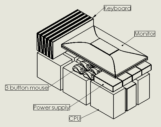
STEP 1. Modeling the Lab Equipment
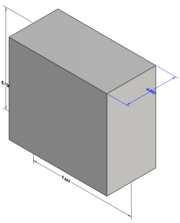
Creating SOLIDWORKS models for the CPU boxes was simple. I took my calipers and measured the maximum distance in the length, width, and height, approximately (9.5” x 8” x 5”)
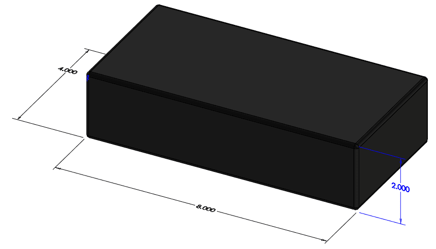
Then I used the same technique to measure and model the external power supply.
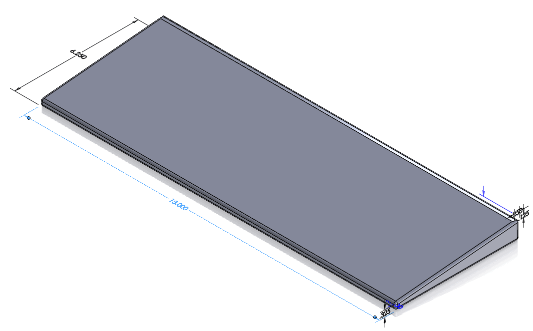
Next, it was time to model the monitors. Although LCD monitors can be awkward, the Dell monitors we have can have their stands removed, so modeling the basic shape of the LCD was also very simple. I started with a basic rectangle then added some shaping cuts.

Next a simple shape for the keyboard.
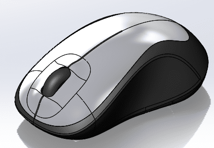
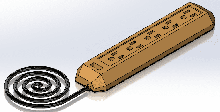
Lastly, I downloaded a mouse model and a simple power strip from 3D content central.
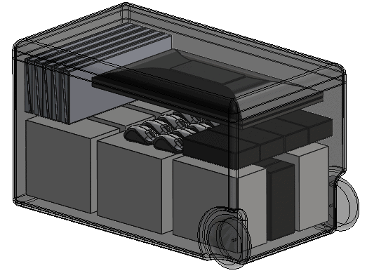
STEP 2 Arranging the Lab Equipment
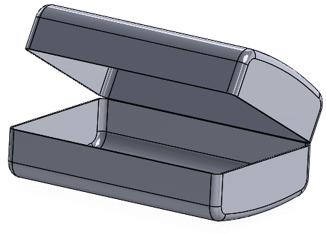
This involved several iterations of placing and arranging the equipment into the existing clamshell. I started by modeling the clamshell case to carry as many of the monitors as possible.
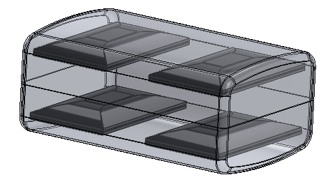
With the container closed, I was able to place 8 of the monitor models inside with about 1 inch of space all around. This was accomplished by creating a sub-assembly with two monitors face-to-face then placing them into the container using distance mates and then using a linear pattern and a mirror pattern.
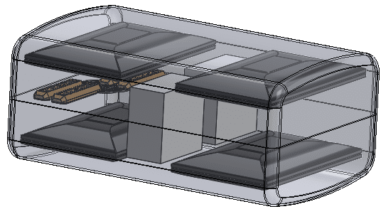
This left room to add 2 CPU’s using the same method and then I used a linear pattern in the space between the top and bottom to insert 4 power strips using the same method.
Next, I took the rest of the equipment and began arranging it into the smallest rectangle I could create by placing a single item then adding a linear pattern, and the monitor sub-assembly.
Then I found and modeled a crate everything would fit into.
With all of the equipment positioned within the containers the next job would be creating the models for the padding to hold it all securely. The process I used to create the padding will be detailed in my next blog article, so stay tuned.
Thanks,
Dennis Barnes | CSWE | CSWI
Application Engineer
Computer Aided Technology, LLC