Flow Simulation Meshing: Global Automatic Settings
One question that arises with users of SOLIDWORKS Flow Simulation is how to create an accurate mesh without an excessive cell count. It is easy to overdo it and end up with a solution that takes far too long to complete or underdo it and not capture important features of the geometry or flow. The global automatic settings can help get started in the correct direction and is the subject of this blog.
First things first! I want to establish a general understanding of the solution method used by SOLIDWORKS Flow Simulation and the process used to develop the mesh, with emphasis on the influence of the global automatic settings. In subsequent blogs I plan to provide a deeper dive into the global manual settings and local mesh control.
The Finite Volume Method…
SOLIDWORKS Flow Simulation uses the finite volume (FV) method to represent fluid and solid volumes with a mesh of three-dimensional rectangular cells. During solution of the Navier-Stokes fluid flow equations, the FV method establishes a balance of mass, energy and momentum at every fluid cell and at the extent of the fluid volume under consideration (the computational domain boundaries). A good FV mesh is a must to accurately capture the solid/fluid boundary and the fluid within the domain.
This method differs from SolidWorks Simulation and other programs that incorporate the finite element (FE) method. A mesh of solid elements represents the bodies of interest and the FE method solves for stress, temperature, acceleration, etc. at nodal points within the mesh.
Easier said than done?
The ease of creating a good FV mesh depends on the geometric complexity. Most simple geometries are easily meshed with the default global automatic mesh function provided in SOLIDWORKS Flow Simulation – these are my favorite to simulate! However, thin passageways and small features important to the simulation require various levels of intervention to get a mesh that works well – call me crazy, but I actually like working with these too!
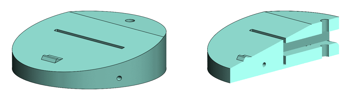
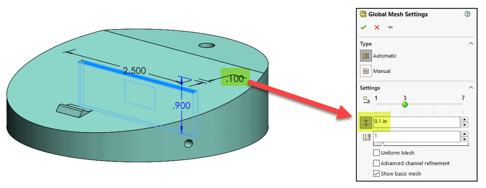
For the purpose of demonstrating FV mesh creation and control I’ve created the part shown below with a cross-section of it on the right. It has some narrow passageways, drilled through holes and a small bump feature on the top angled surface.
Back to the basics!
Upon project creation Flow Simulation generates a “basic mesh” which acts as a starting point for the meshing process. Cell size for the basic mesh is based on the overall dimensions of the geometry. After creating an external analysis project for my part, the basic mesh and global coordinate system triad were turned on (right click on the project name in the tree to activate these). The basic mesh is three-dimensional but is projected onto the three orthogonal system planes to avoid clutter.
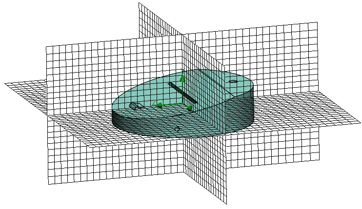
At this point, only the extents of the domain have been resolved. Geometry resolution is the job of the subsequent “initial mesh” – more on that in a bit.
Under the hood…
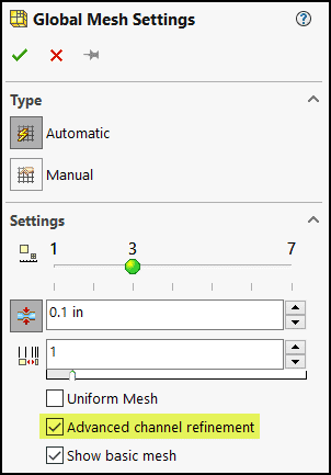
Right-click on the global mesh and select “edit definition” to open the settings property manager. This is where the size of the cells in the basic mesh can be measured and manipulated. Notice the small square in the lower right corner of the graphics area. Picking that icon and then hovering over a cell shows its size in the units set during project creation. The slider in this interface is used to control the basic mesh cell size. The slider position “3” is the default setting and usually a great starting point for any project.
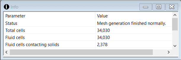
The next step is to create the “initial mesh” and capture the geometry. After accepting the settings shown above, right-clicking on the mesh icon and selecting “create mesh” will start the process. This will open the solver monitor window and show the progress of initial mesh creation. (Using this method will only mesh the project without the option to start the solution, which allows you to evaluate the mesh before committing to the solution.) The program produced 34,030 fluid cells; 2,378 of them are in contact with the solid. A mesh section plot showing the refinement level reveals that the geometry wasn’t captured well using the default mesh settings.
This mesh requires additional refinement for the following reasons:
- The fluid boundary in the 0.125-in. diameter, drilled hole is not circular.
- There are only two cells across the small passageways. (Ideally, narrow flow paths should have several cells across.)
Digging deeper…
An additional setting designating the minimum gap size to be resolved is available in the global mesh property manager and can be used to resolve the above conditions. The smallest gap in this model is the 0.1-in. vertical slot width.
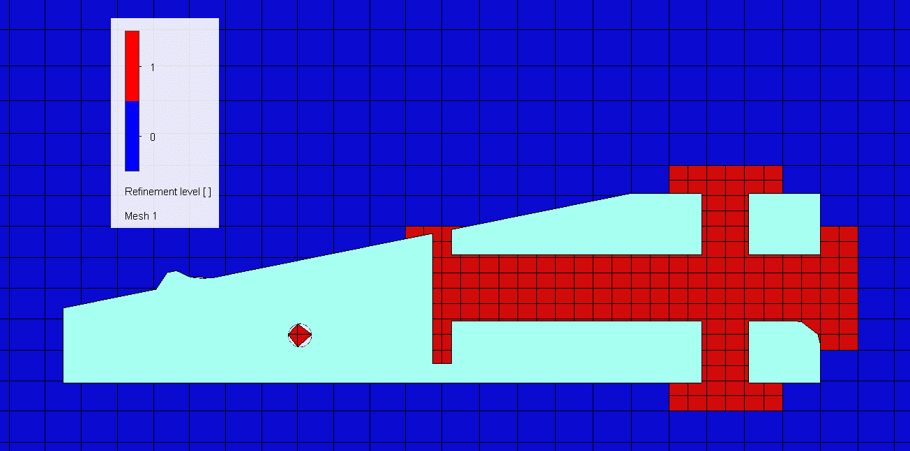
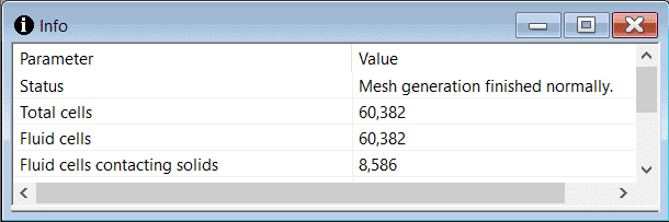
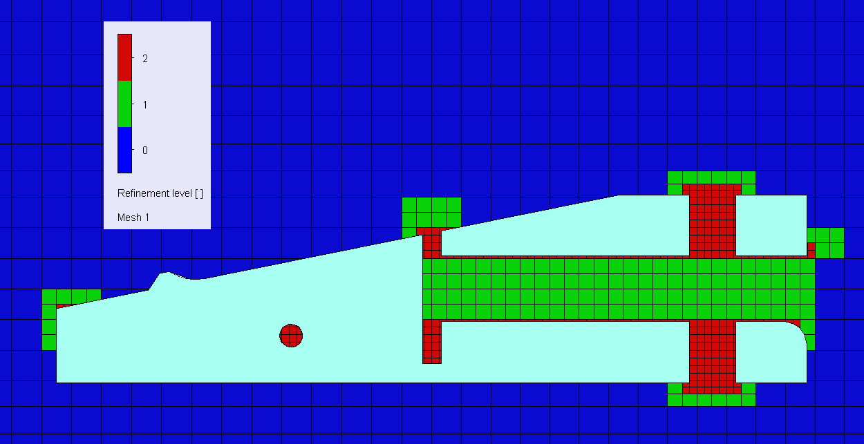
Using this value in the minimum gap size setting and remeshing the project produces a mesh with an additional level of refinement in the narrow flow paths. The mesh cell count increased to 60,382 fluid cells (8,586 contacting solids); however, both the hole and small vertical passageway still have only 2 cells across.
Third time’s a charm!
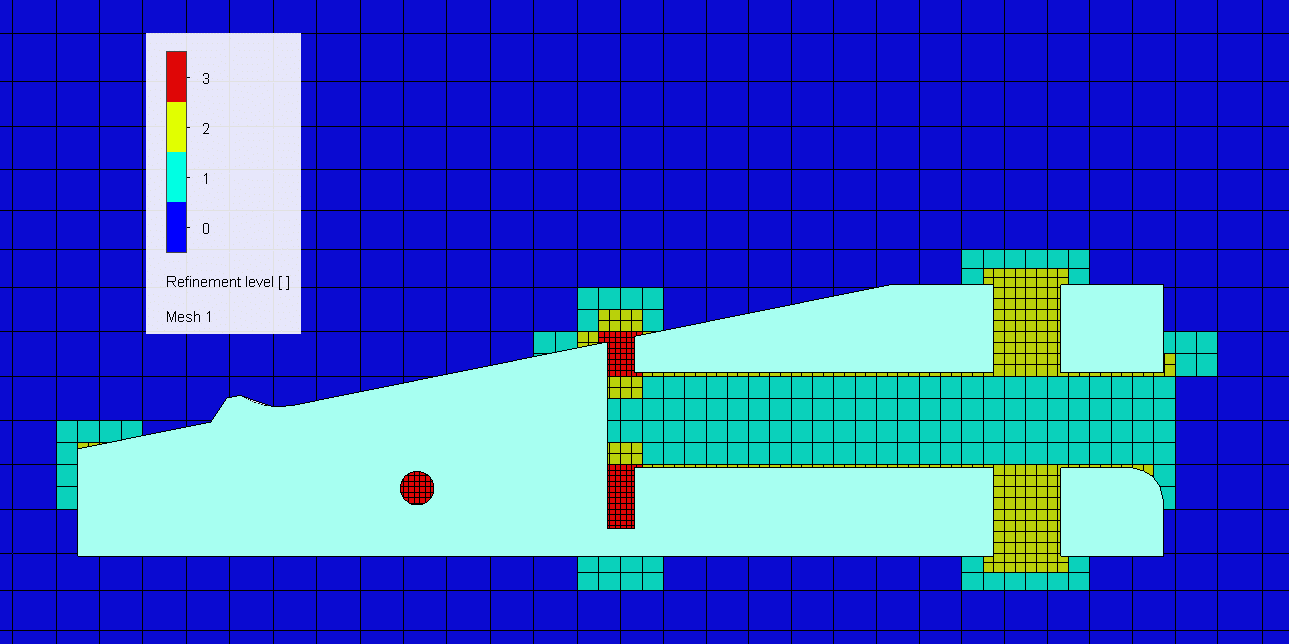
“Advanced channel refinement” is another global automatic setting that can increase the number of cells in these areas. Activating it increases the refinement level by one for narrow channels. (Narrow channel designation is determined internally by the program based on the “level of initial mesh” slider and the dimensions of the geometry.)
Remeshing with this change resulted in creating 89,555 fluid cells (19,466 contacting solids), with the small passageways adequately resolved.

At this point, there are a few features like the small bump on the top surface that could be resolved better before running a solution. One technique for doing so is with the use of local mesh control, as discussed in a blog by my colleague Robert Warren. Other techniques involving the global manual settings will be discussed in future blog posts. In the meantime, experiment with what you’ve learned here about the global automatic mesh settings to improve your SOLIDWORKS Flow Simulation meshes.
Kurt Kurtin
Sr. Product Manager, Simulation
Computer Aided Technology, Inc.