How to Create a SOLIDWORKS Electrical Route
I showed you how easy it is to create a simple Piping Route last month. Let me show you how easy it is to create an Electrical Route.
First off. What is an Electrical Route? SOLIDWORKS Routing is the creation of electrical wiring, cabling, conduit and tubing routes. SOLIDWORKS Routing is a package that is available with all Premium Licenses.
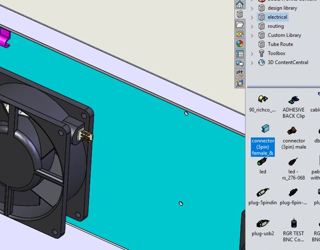
The first thing we need to do is drag and drop a connector from the design library to an existing component in an assembly. Select the configuration that’s needed.
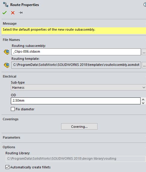
The Route Properties appears automatically. The Route Properties dialog box is used to set the name of your sub-assembly and the properties used in the route. This includes the electrical type, covering and other parameters. I’ll use the defaults and hit the green check mark.
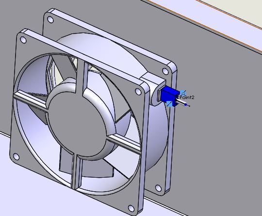
Notice the “stub line” that was created.
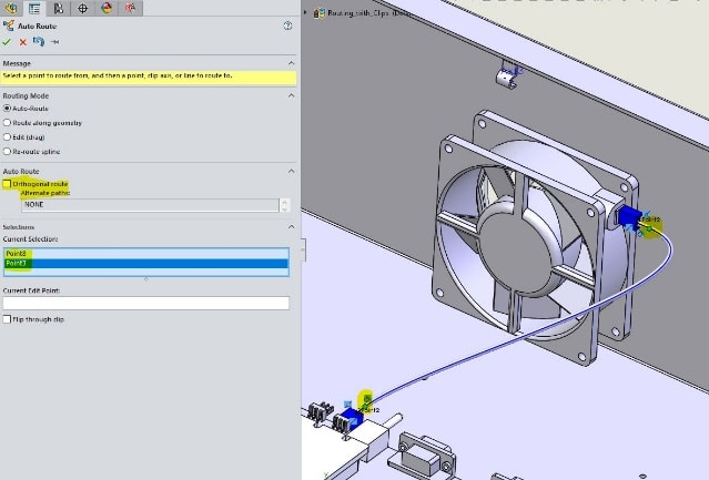
Next, the Auto Route property manager pops up. At this point, we can drag and drop another connector. Make sure Orthogonal route is unchecked and select the “stub” endpoints of the connector.
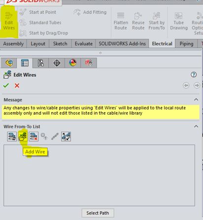
Now let’s look at the Electrical Attributes. Right-click the spine and click Electrical Attributes. You will notice the wire list is empty. This is because we need to assign the wire data to the route path. Click the green check to exit Electrical Attributes. Click Edit Wire from your Electrical command manager tab and click Add Wire.
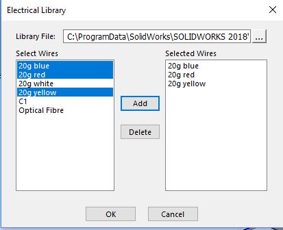
In this case, we have a twisted cable with 3 wires. Select the 20 G Blue, Red and Yellow wires from the Select Wires and click Add. This adds the wires to the Selected Wires list. Click ok.
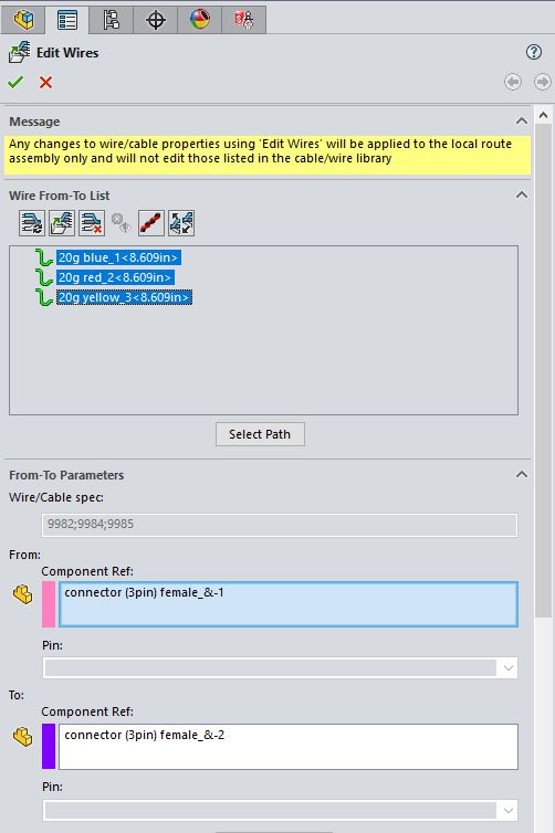
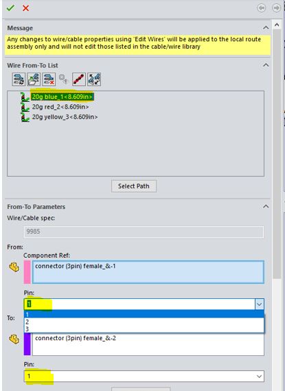
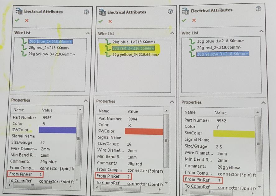
The Edit Wire property manager pops up. Notice the Unassigned wire warnings next to the wire. Select all three wires and click Select Path. Select the spline as the Select Segments and hit the green check mark. Notice the Assigned Wire symbol next to the wire. Also, notice the connectors are now assigned as the From and To Referenced Components. We will now use the Pin options to manually assign the pins for each wire. Select the 20G Blue wire and assign it as pin 1. Assign the other two wires to the pins. Hit the green check mark.
Let’s look at the Electrical Attributes now. The wires and associated properties including the pins appear in the Wire List.
Exit the route sketch and the route subassembly.
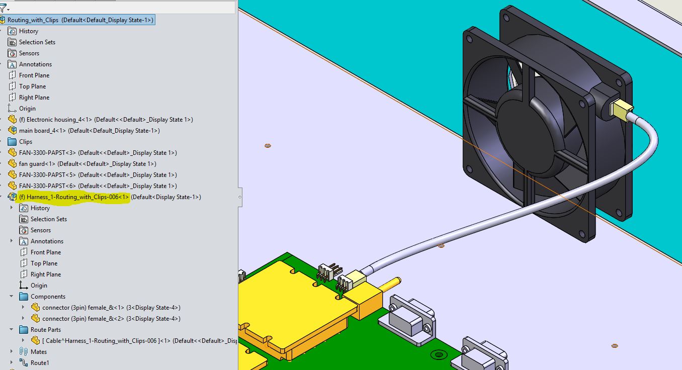
There you have it, SOLIDWORKS makes creating an Electrical Route that easy.
Roger Ruffin
Sr. Application Engineer
Computer Aided Technology, LLC