Neutral Axis, Shear Center and Beam Meshing in SOLIDWORKS Simulation
Beam meshing has been available in SOLIDWORKS Simulation for many years and is an excellent way to represent structural members in the analysis of frame assemblies. Beams are one dimensional line elements that incorporate the cross-sectional properties of the member into the element formulation instead of explicitly capturing the details as with a solid mesh. This allows the efficient calculation of axial, shear and bending stresses within the member, whereas a solid mesh can become prohibitively large since it requires at least 2-3 high quality elements through the thickness of the cross section.
Two key features of the beam element formulation, neutral axis and shear center, are highlighted in this blog. SOLIDWORKS Simulation includes them in static structural analyses. Here are definitions of each from the classic text by W.C. Young, Roark’s Formulas for Stress and Strain, 6th Edition.
Neutral Axis: The line of zero fiber stress in any given section of a member subject to bending; it is the line formed by the intersection of the neutral surface and the section.
Shear Center (called “Flexural Center” by Roark): The point in the plane of the section through which a transverse load, applied at that section, must act if bending deflection only is to be produced, with no twist of the section.
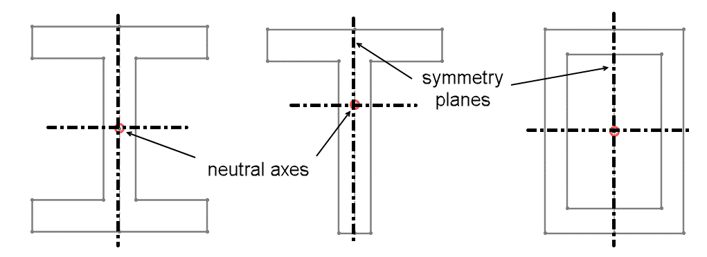
For vertically symmetric sections “I”, “T” and rectangular geometries shown below, when loaded vertically the shear center coincides with the neutral axis and lies in the plane of symmetry. Thus, bending loads on beams with these geometries produce deflection without twist.
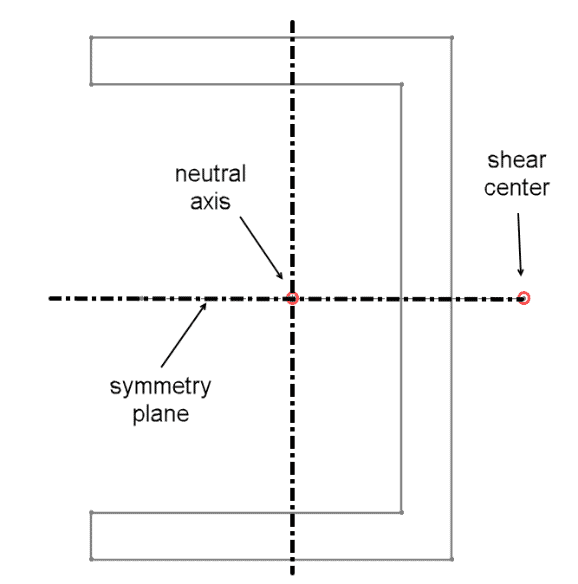
For open sections, this is not the case. Roark and Young provide a table (Table 14) that shows the position of the shear (flexural) center for different sections. For a “C” section the neutral axis is inside the channel, but the shear center is outside. Therefore, if a C-channel beam is loaded vertically through the neutral axis it will bend and twist, but if loaded through the shear center it will only bend.
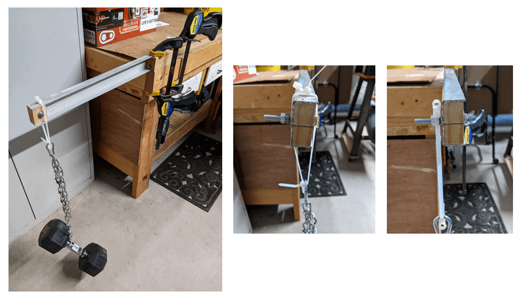
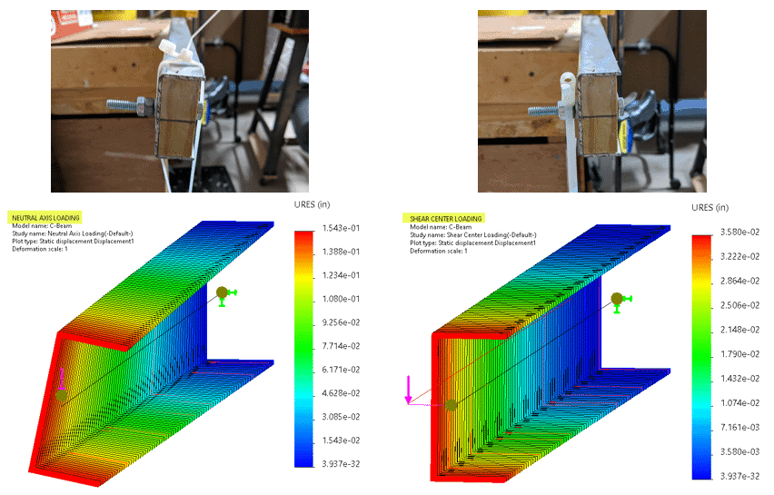
The physical test shown below demonstrates this behavior. An 18-inch long 2-inch by 1-inch cantilevered C-channel beam was loaded with 25 lbs. through the neutral axis in one case and through the shear center in another. When loaded through the neutral axis, the expected twist is observed. To determine the approximate location of the shear center (about ¼ inch outside the web of the channel), the load was shifted until the beam did not twist.
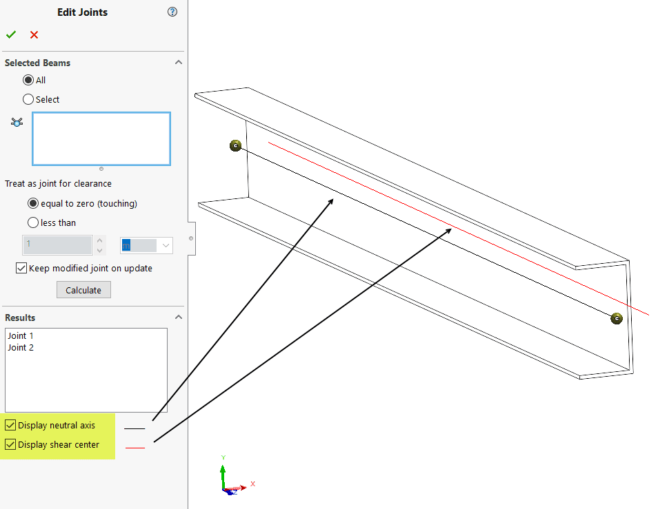
Using SOLIDWORKS Simulation this effect was demonstrated with a model of the physical test setup. The neutral axis and shear center locations are calculated by Simulation automatically. Within the “Edit Joints” property manager toggling two check boxes will show their location in the graphics area. The beam joints lie on the neutral axis. The shear center is outside the channel web.
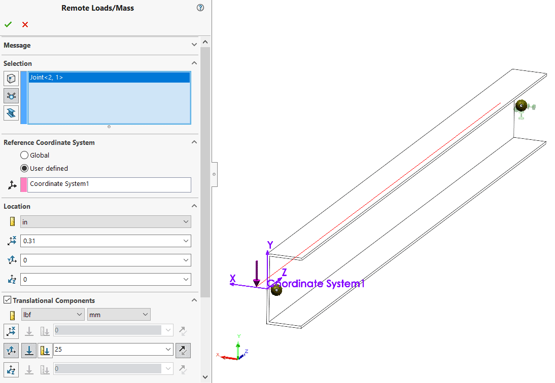
Two studies were created for the C-channel beam with the load applied at the neutral axis and the shear center, respectively. In the former, the load was applied directly to the end joint, which coincides with the neutral axis. In the latter, a remote load was used to offset the point of application to the shear center as shown below.
Deflection result plots for each loading case are shown below. Measured deflections in the physical test were slightly greater than calculated due to the added deflection of the wooden bench and the flexibility of the clamping method. The intent of the test was to show the twisting tendency under the load applied through the neutral axis and the pure bending for the case with the load applied through the shear center.
This is one example of how SOLIDWORKS Simulation includes important details needed for a robust and accurate structural analysis using beam elements. An efficient mesh is key; remember that it is possible to create a study with a mix of solids, shells and beams for assemblies with bulky and thin members.
I hope this information has motivated you to make use of beam meshing in your structural simulations. Please check out our other CATI blog articles related to beam joints, shear and bending moment diagrams and thermal loading. Thanks for reading!
Kurt Kurtin
Sr. Product Manager, Simulation
Computer Aided Technology, Inc.