SOLIDWORKS 2020 What’s New – Create Multiple Connection Points
In SOLIDWORKS 2020, you can now create multiple connection points in a part.
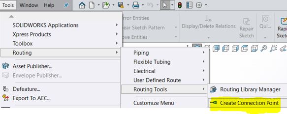
It’s really easy to do. Let’s get started. Click Tools>Routing>Routing Tools and click Create Connection Point.
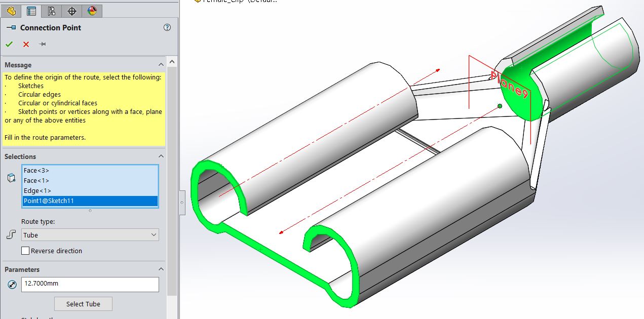
To create multiple connection points, select the following parameters.
- A sketch that has sketch points. The number of connection points is equal to the number of sketch points in a sketch.
- Multiple circular edges.
- Multiple circular and cylindrical faces.
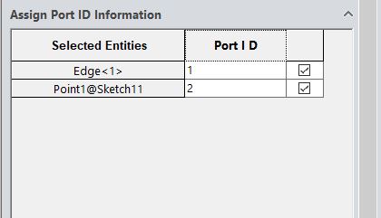
You can also assign a port ID or pin information to the connection points. Scroll to the bottom of the Connection Point property Manager
When the Tube and Fabricated Pipe route type, it displays the Assign Port ID Information section.
When the Electrical route type is selected, it displays the Assign Pin Information section.
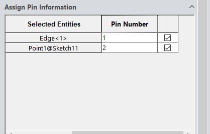
- Selection Entities display the entities from the selection list
- CPoint Name displays the connection point name, which can be edited.
- Port ID or Pin Number displays the port ID or pin number, which can also be edited.
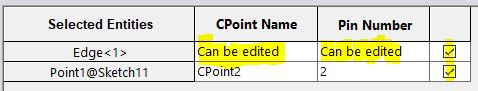
Make sure to select the checkbox for each row to create the connection point.
When you select or edit the CPoint or ACPoint they are highlighted in the graphics area and in the FeatureManager design tree.
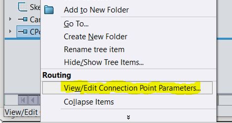
With a part or assembly open that has these parameters, you can access View/Edit Connection Point Parameter dialog box.
Right-click CPoint and click View/Edit Connection Point Parameters.
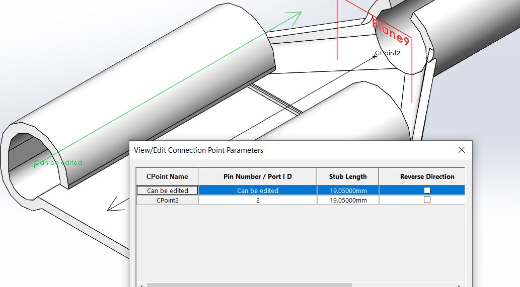
- CPoint Name displays the connection point name.
- Pin Number/Port ID displays the pin number or port number, which you can edit.
- Stub Length displays the stub length, which you define when you create connection points. You can edit the stub length.
- Reverse Direction reverses the direction of the route.
For assembly connection points, you can edit only the Pin Number/Port ID.
I hope this part of the What’s New series gives you a better understanding of the new features and functions of SOLIDWORKS 2020. Please check back to the CATI Blog as the CATI Application Engineers will continue to break down many of the new items in SOLIDWORKS 2020. All these articles will be stored in the category of “SOLIDWORKS What’s New.”
Design Innovation Month – October 2019
What is DI Month? We’re declaring October Design Innovation Month—again! It’s a month-long series of special events focused on what’s new in design and manufacturing technology. You’ll learn about enhancements in SOLIDWORKS 2020 that deliver new capabilities for improved performance, streamlined workflows, and a connected design ecosystem. Find out what’s new in 3D printing applications and 3D scanning to integrate into your design process. So, get ready to do things differently. It’s time to innovate!
Roger G. Ruffin
Senior Application Engineer
Computer Aided Technology, LLC