SOLIDWORKS 2020 What’s New – SOLIDWORKS CAM
![]()
What’s NEW in SOLIDWORKS CAM Standard 2020
New – Support for Tabs Cutting in Contour Mill Operations in SOLIDWORKS CAM Standard 2020
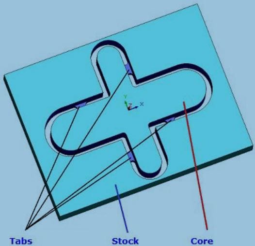
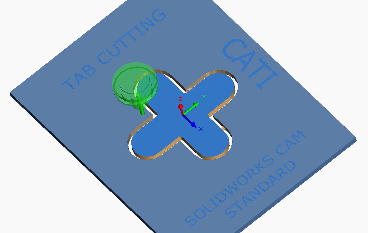
Allows users to define tabs on the feature profile of a through mill feature machined using a single Contour Mill application. The “Tab” feature consists of a small piece of the stock material along the profile (feature boundary) of the part. By keeping the core material and/or part attached to the stock material with the tabbing feature, the contour milling will cut the entire profile of the feature. This keeps the part from dropping from the stock material and potentially damaging the part and/or its finish. The Tab feature in SOLIDWORKS CAM 2020, is a great solution for solving this issue.
YOU NO LONGER NEED TO DEFINE AVOID AREAS – Yeah!
‘Tab Cutting’ group box under Contour Tab of a Contour Mill Operation
Within SOLIDWORKS CAM 2020, in order to enable the Tab feature and begin defining milling tabs, click the check in the Tab Cutting checkbox. The Settings button within this group box will be enabled only when the Tab Cutting checkbox is checked. Clicking on this button displays the Tab Settings dialog box.
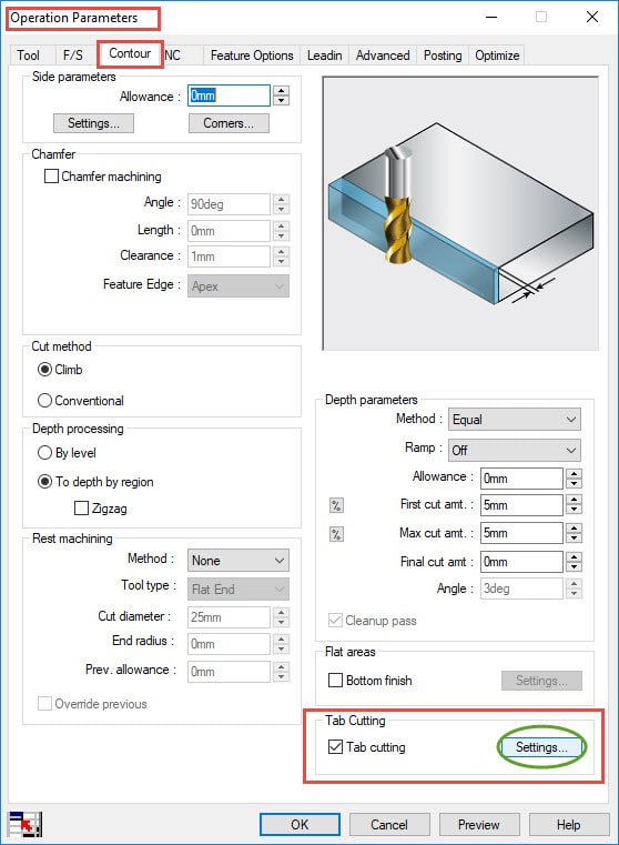
NOTE: Mill Tabs can be applied only when the option of Bottom Finish is selected.
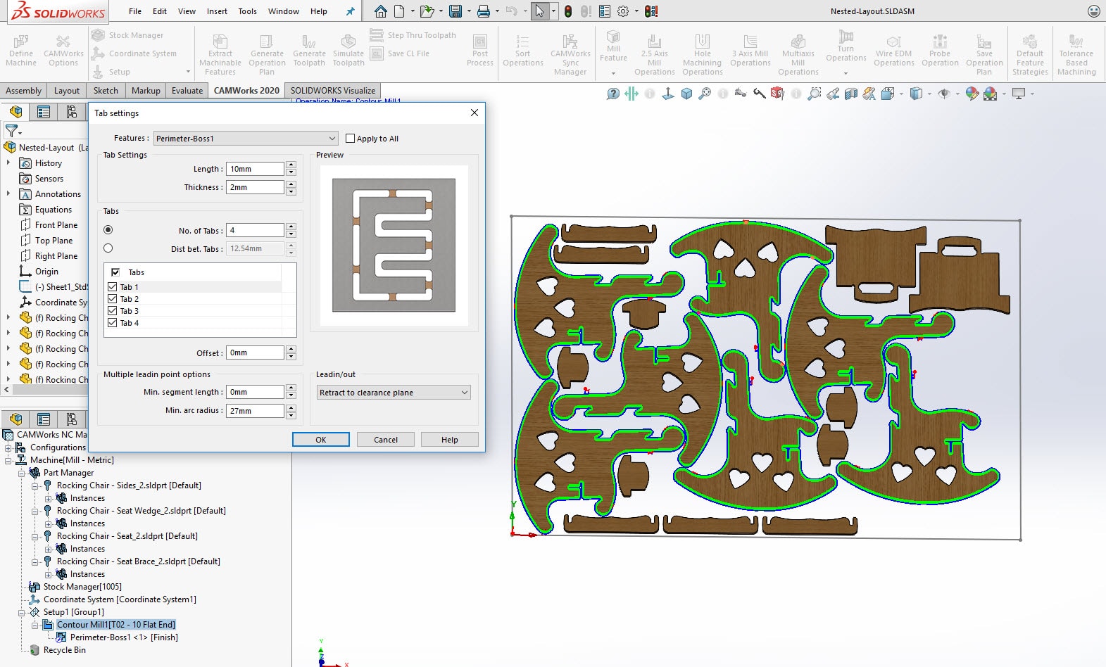
Milling Tab Feature Settings Dialog Box in SOLIDWORKS CAM 2020 User Interface
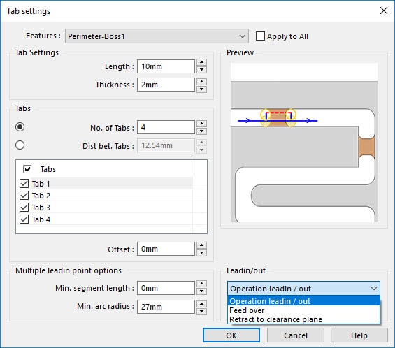
Tab Settings Dialog box provides the options and controls for defining multiple tabs along the feature profile. So the core is retained with stock.
A list of settings below which can be assgined for the Tab feature:
Selecting the feature for which tabs are to be generated
- Selecting the feature for which tabs are to be generated ==> Applicable only when a group features or multiple mill features are machined by the Contour Mill operation
- Indicating whether the settings in Tab settings dialog box are to be applied to a specific feature being machined by the Contour Mill operation or to all the features being machined by the Contour Mill operation ==> Click “Apply to All” checkbox option
- Can define tab dimensions by ==> Length and Thickness parameters
- Number of tabs to be generated along the feature to the edge of the object ==> No. of Tabs parameter box
- Can offset the default location of specific individual tabs along the edge of the feature ==> Offset parameter
- Able to select tab in the graphics area ==> Tabs list box
- By deselecting specific tabs, their toolpaths will not be generated ==> Checkbox options in the Tabs list box
- Can specify number of tabs to generate along the segments/arcs that coonsist of the edge of the feature ==> Minimum Segment Length and Minimum arc radius parameters
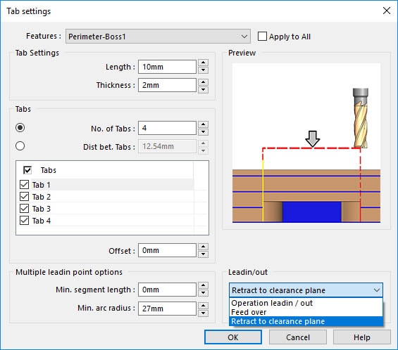
- Defining the exit and entry method for the toolpath so that the tool can retract and enter into the stock material at the tab locations ==> Leadin/out dropdown list
Tabbing shown after running SOLIDWORKS CAM machining simulation
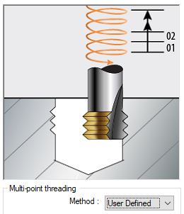
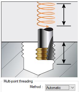
New – Tapered Multi-Point Thread Mill tools are now supported in SOLIDWORKS CAM Standard 2020
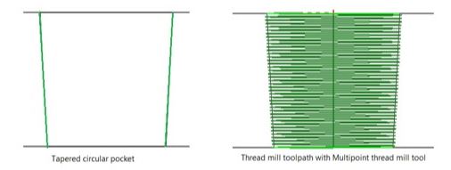
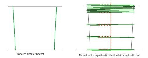
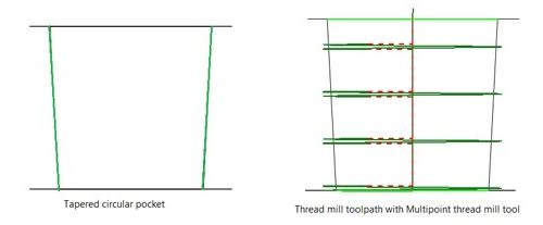
Prior to SOLIDWORKS CAM 2020 and CAMWorks 2020, the tapered multi-point thread mill tools were not supported. But now in SOLIDWORKS CAM 2020, tapered multi-point thread mill tools are supported. Such as thread mill toolpaths for circular boss. Circular pocket and hole features can now be machined using multi-point thread mill tools.
For a Thread Mill operation machined with a Tapered Multi-Point Thread Mill tool, the following parameters in its Operation Parameters dialog box will be affected.
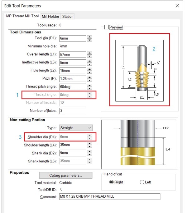
Multi-Point Thread Mill Tool page under Tool tab:
- Existing tools can accommodate taper
- Flexible toolpath patterns
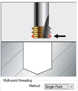
- The Thread Angle parameter will be enabled when Type in the Non-Cutting Portion group box is set to Tapered. This parameter defines the angle of the multi-point tapered thread mill as defined from the vertical.
- The Shoulder Diameter will be equal to the inner diameter of the largest thread on the tool.
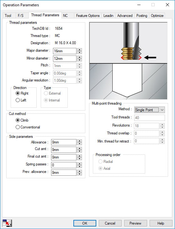
Thread Parameters group box under the Thread Parameters tab:
- The Taper angle parameter will be disabled and will be assigned the value defined for the Thread Angle parameter in the Multi-Point Thread Mill Tool page under Tool tab.
- The Angular Resolution parameter will be enabled when the value assigned to the Thread Angle parameter is greater than zero. This parameter defines the angular resolution or smoothness of the point-to-point toolpath by specifying the maximum angular rotation of each move, as seen from the XY plane. If the angle assigned to this parameter is X degrees, then the number of point-to-point linear moves in the thread mill toolpath will be (360/X).
New – Options to Save and Restore Customized TechDB UI in Technology Database in SOLIDWORKS CAM Standard 2020
You will have options to edit the tabular layouts within the TechDB and save the customized layouts so that users can consume the displayed data as per their desired custom settings
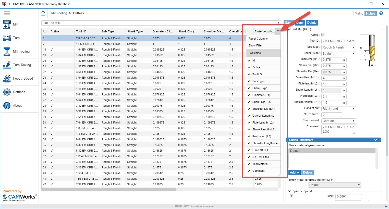
Within the TechDB user interfaces, parameters pertaining to various entities (like features, operations, tools, machines, etc.) is displayed in a tabular grid format. These grids can be customized to suit your display requirements. These settings include:
- Adjusting the width of the columns
- Rearranging the order of the columns
- Displaying only specific columns
- Hide / Show columns
- Resize Columns
- Auto resize on double click
- Relocate Columns
- Filters stay active
- Save these UI settings
- Reuse the UI settings
The custom grid display settings are loaded whenever you launch the TechDB. They are retained even when data is imported from another TechDB.
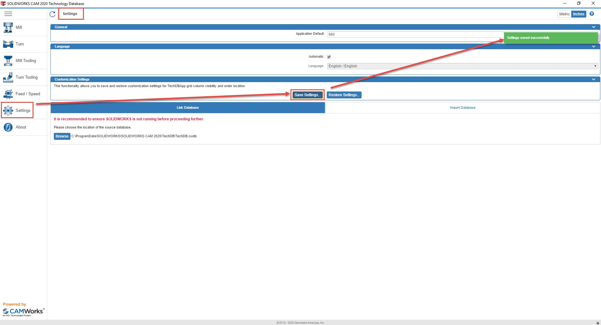
From SOLIDWORKS CAM 2020 version onwards, SOLIDWORKS CAM provides functionality where you can save your TechDB custom settings, such as:
- The custom settings for the grid display can be saved as an external file (*.cwjs)
- The grid layout of any other TechDB App can be customized by restoring/applying a previously saved external *.cwjs file.
This functionality is provided in the form of the ‘Save Settings’ and ‘Restore Settings’ buttons in the TechDB Settings user interface.
New – Posting in SOLIDWORKS CAM Standard 2020 – Enhanced Universal Post Generator (named “UPG-2”)
Enhanced Universal Post Generator (UPG) installer named UPG-2 with support for Probing Cycles and Subroutines
PLEASE NOTE: From SOLIDWORKS CAM 2020 version onwards, the older versions of Universal Post Generator will no longer be supported. In its place, an enhanced version of UPG named UPG-2 will be available.
UPG-2 is built using technologies that are compatible with modern Operating Systems. It has the same structure, concepts, and methodologies as the old UPG. Users will not find any difference in the user interface of this application.
- Post processors compiled using UPG-2 will be compatible with older SOLIDWORKS CAM versions, prior to SOLIDWORKS CAM 2020.
- For better compatibility, UPG-2 gets installed as a separate installation and will not overwrite an older version of UPG.
UPG-2 also comes equipped with the enhancements required to support Probing and Subroutines in SOLIDWORKS CAM 2020 version.
Everything I’ve previously talked about in this blog has been about What’s New with SOLIDWORKS CAM Standard 2020. The following I will be talking about will be what is included in SOLIDWORKS CAM Professional. Please note, the previous features I talked about new in SOLIDWORKS CAM Standard are also available in SOLIDWORKS CAM Professional 2020.
![]()
What’s NEW in SOLIDWORKS CAM Professional 2020
SOLIDWORKS CAM Professional 2020 will support for Probe Tools and Probing Operations. The functionality of Probing Operations using Probe Tools for Milling. Probing is an established best practice for maximizing the efficiency, quality, capability and accuracy of machine tools. Going forward from 2020 and on. SOLIDWORKS CAM Professional and CAMWorks Standard, CAMWorks Milling Professional, CAMWorks Turning Professional and CAMWorks Premium versions, probing operations will be supported for Milling.
New – Probe Tools for Probing Operations in SOLIDWORKS CAM Professional 2020
A new type of tool named Probe Tool will be available in the SOLIDWORKS CAM/CAMWorks Tool Library. Probe Tools can also be defined and saved in the TechDB. To assign Probe Tools to Probing operations, the desired Probe Tools can be added to the Tool Cribs in the SOLIDWORKS CAM/CAMWorks user interface as well as the TechDB.
- New Probing tool types added
- Renishaw touch probes are added in TechDB
- Few OMP, RLP holders added to TechDB
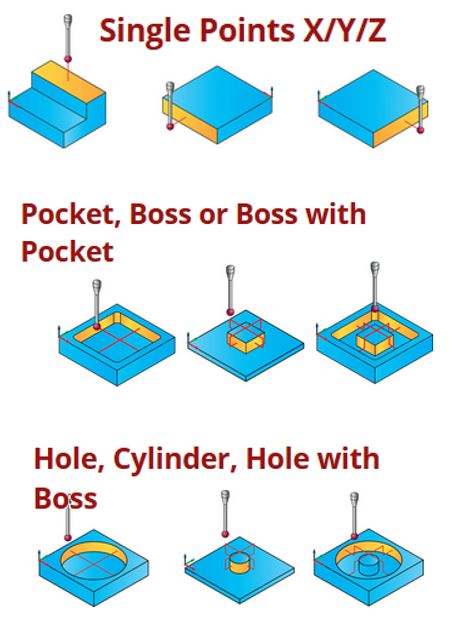
- Probing Supports
-
- Single point (X, Y, Z)
- Pockets with islands
- Boss
- Holes
- Circular boss
- Can be used to update Work offset
- Will be part of CAMWorks and SOLIDWORKS CAM Pro
- No separate module
- New Operation type – Probe Operation
- Intelligent picking
- No need to predefine features
- Defaults can be saved to TechDB
- Current defaults are from Renishaw manual
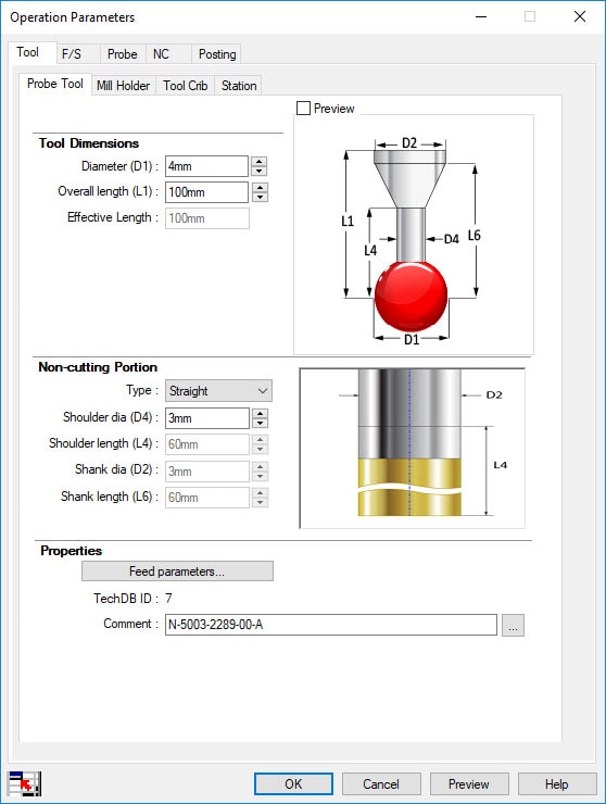
To edit the parameters associated with a Probe Tool, use either the Probe Tool tab in the Edit Tool Parameters dialog box or Probe Tool page under Tool tab of the Operation Parameters dialog box for a Probing Operation.
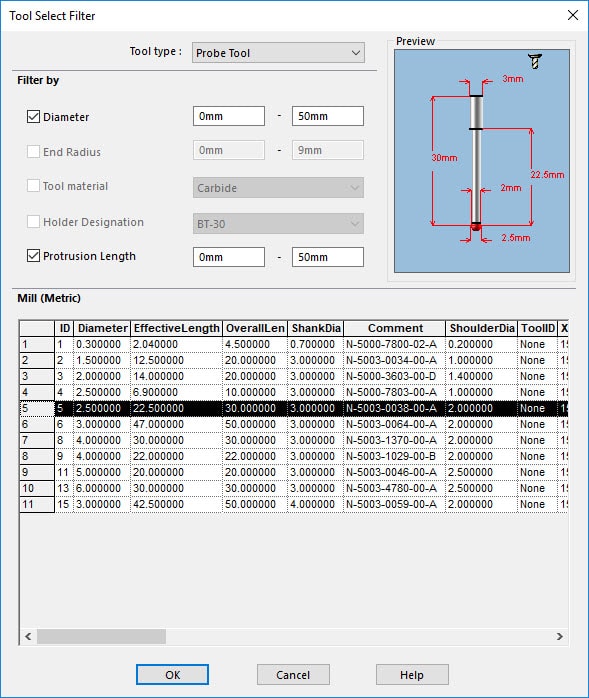
‘Tool Select Filter’ dialog box when a Probe Tool is selected
Probing Operations can be interactively inserted by executing the Insert Probing Operations command on the CAMWorks Command Manager. Alternatively, this command is also available in the Operation tree in the form of the Probing Operation command in the RMB context menu of the Mill Part Setup and Operation nodes.
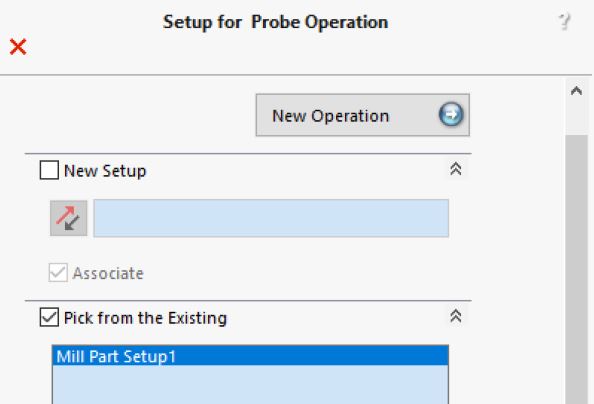
Executing this command displays the Setup for Probe Operation dialog box. Use this dialog box to either define a new Setup or pick an existing setup under which the Probing operation is to be listed.
Setup For Probe Operation dialog box
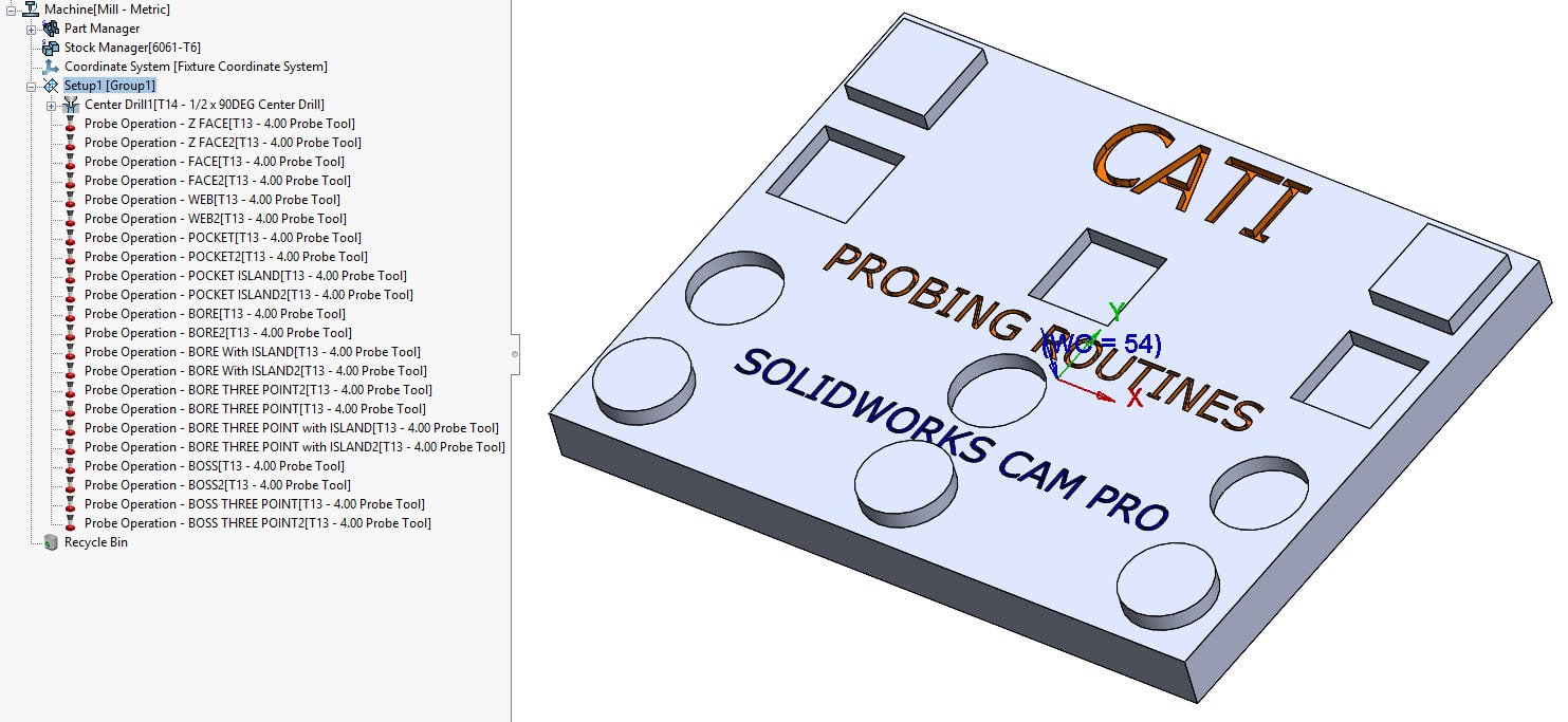
Setup with Probing Operations added
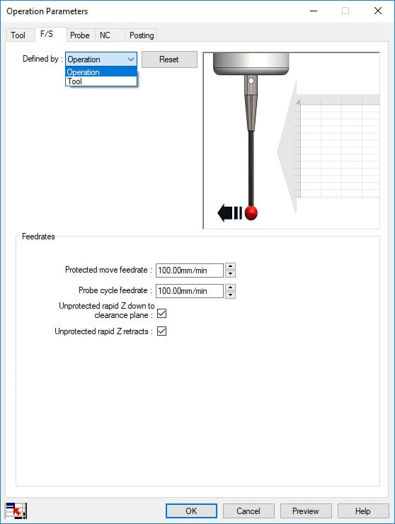
F/S tab in Operation Parameters dialog box for Probe Operations
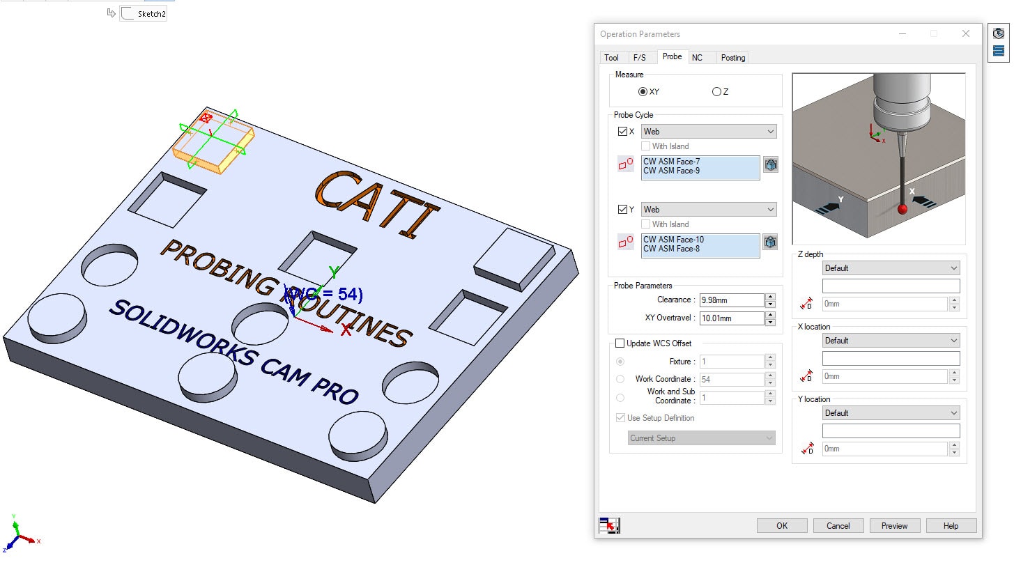
Probe tab in Operation Parameters dialog box for Probe Operations
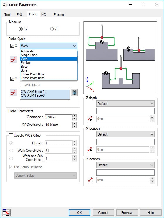
Probe tab in Operation Parameters dialog box displaying types of Probing Cycles available. Can measure in X & Y directions and/or in the Z direction
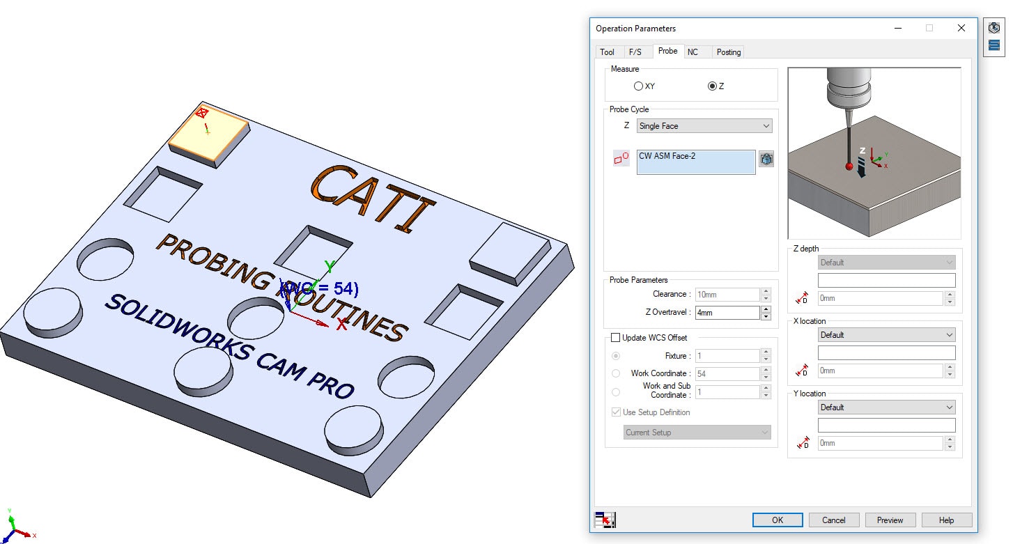
Probe tab in Operation Parameters dialog box displaying the Single Face probing cycle measuring in the Z direction
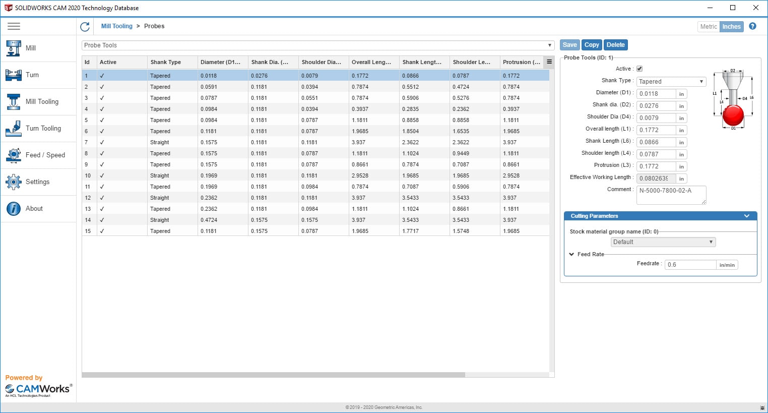
The default Milling Probing Tools included with the SOLIDWORKS Tech Database (For Inch and Metric Mill Tooling)
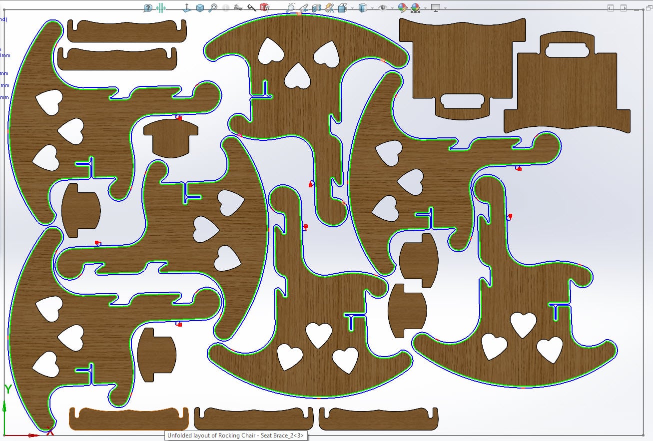
New – Using Tabbing in SOLIDWORKS CAM Professional 2020 for Assembly Machining
Previously in this blog, I mentioned it was supported in the SOLIDWORKS CAM Standard 2020 for mill parts only. Tab Cutting in Contour Mill Operations is also available in Assembly Machining which is included in SOLIDWORKS CAM Professional and CAMWorks licenses. The Tab Cutting featue will also come be very handy when using CAMWorks NESTINGWorks with SOLIDWORKS CAM Professional for assembly programming and nesting parts.
I hope this part of the What’s New series gives you a better understanding of the new features and functions of SOLIDWORKS 2020. Please check back to the CATI Blog as the CATI Application Engineers will continue to break down many of the new items in SOLIDWORKS 2020. All these articles will be stored in the category of “SOLIDWORKS What’s New.”
Design Innovation Month – October 2019
What is DI Month? We’re declaring October Design Innovation Month—again! It’s a month-long series of special events focused on what’s new in design and manufacturing technology. You’ll learn about enhancements in SOLIDWORKS 2020 that deliver new capabilities for improved performance, streamlined workflows, and a connected design ecosystem. Find out what’s new in 3D printing applications and 3D scanning to integrate into your design process. So, get ready to do things differently. It’s time to innovate!
Don Glaske
Field Technical Services Manager & CAM Product Manager
Computer Aided Technology, LLC