SOLIDWORKS – Bottom up Assembly vs Muti-body vs Weldments
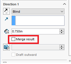
If you are a blog follower of mine, you may recognize these parts. The goal of this article is to build the same parts using weldments to showcase the different design methods and why using weldments is advantageous. The last blog article “Using Reference Planes for Home Made Jerk Blocks DIY” I designed the blocks using my other blog article “Set Up Reference Planes”. This blog got my planes set up to give me basic boundaries to work in. I was able to leverage those planes to easily make configurations of the part, put them into an assembly and see what combinations would work. I kept everything multi-body by deselecting the “Merge” on various extrusions, or cuts.
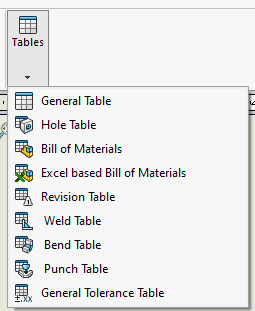
This worked out really well for making parts and getting a general idea of how things would fit together, but the main issue is that my drawing is lacking in important details that I could get if I used weldments. This is my bill of materials for the part if I used a multibody design:
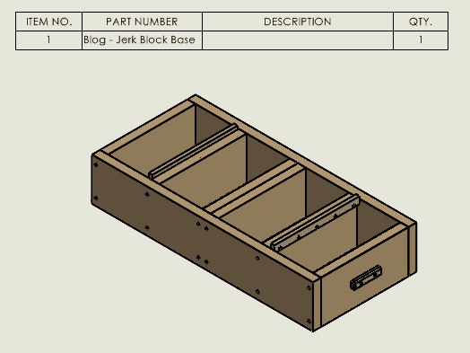
Here is my bill of material for the assembly and as you can see, I do not get any detail about the cut lengths:
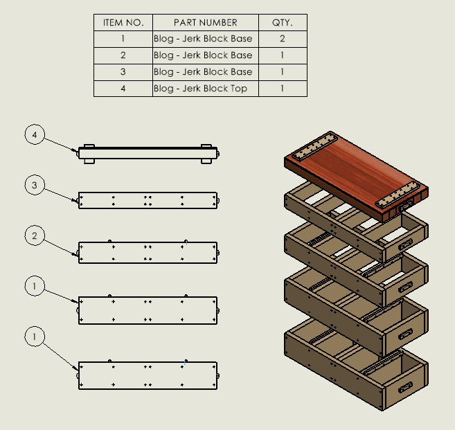
Even if I would have done each part as a strict bottom-up assembly, I would not get any cut details. The bill of materials (BOM), however, would be much better and look something like this and give me a quantity is a plus:
Also, a cut-list is not available as a table option, and I would have to manually add those values into the part property field to pull those numbers into the BOM. Talk about time consuming and imagine all the work you do just in time for a change.
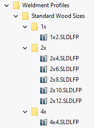
I got useful things out of my first iteration like footprint, what combination of boards to use, but I really wanted a cut-list with that information and just a multi-body part was not going to get me there. To show you the differences I then made the whole thing again but using just weldments as much as possible. First step was to created weldment profiles of the cross-sections of the boards that I will be using as I did not have those in my library yet.
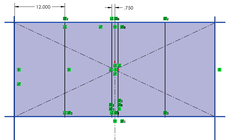
Next, I drew out the base block and tied those dimensions to my Length and Width planes that were set up from my past article. The height is going to be taken care of with the weldment profile, so at this point we will not have to tie anything to that plane.
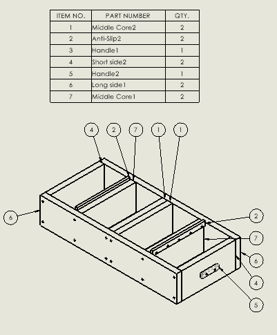
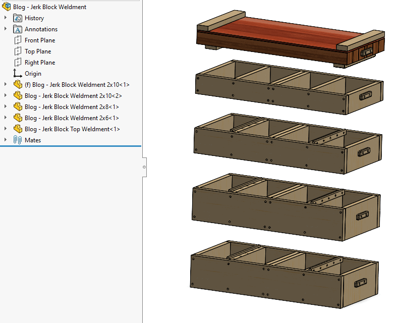
I made each section its own part to help with the BOM at the assembly level. The resulting part looks identical to my first iteration, which is my goal to compare these methods.
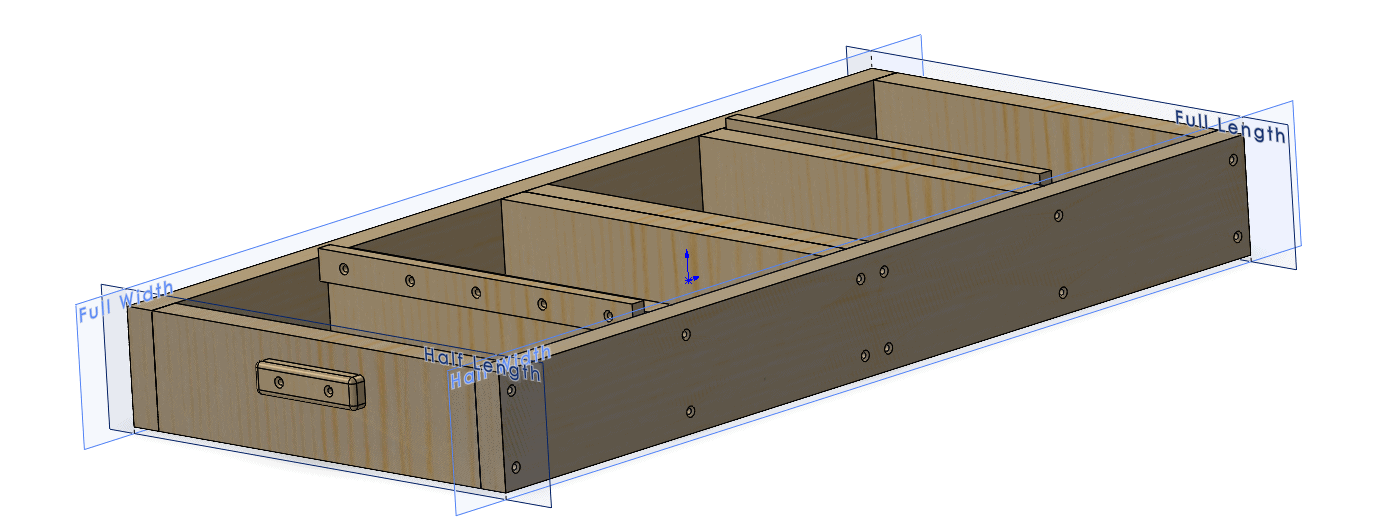
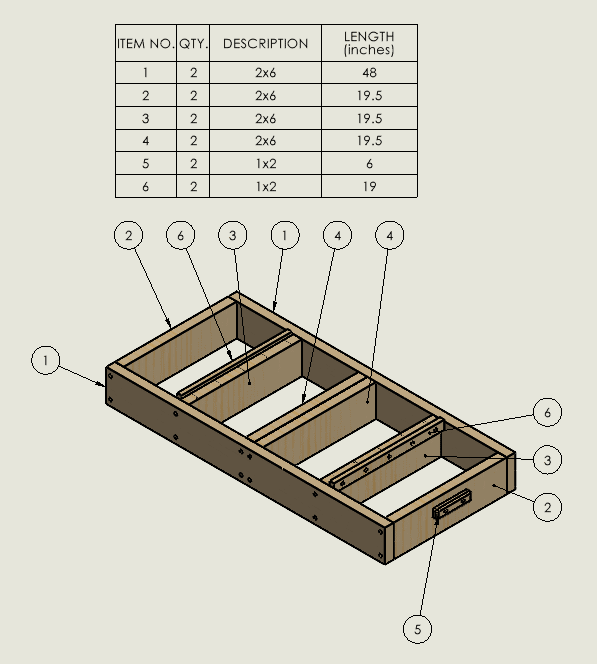
There is no physical difference of my part, but I can get more data out of my tables using the weldment design methods. In short, a weldment table acts as a PART bill of materials for weldments and sheet metal. I also get cut-lengths of each piece from my part, and SOLIDWORKS also knows which parts are unique from each other and groups them accordingly. Items 2, 3, and 4 all have the same length, but different holes for the handles and location boards.
Now I can save, copy the file, and change the weldment features to get different heights of the jerk block sections to make the other height segments. Then to the Assembly where everything fits together.
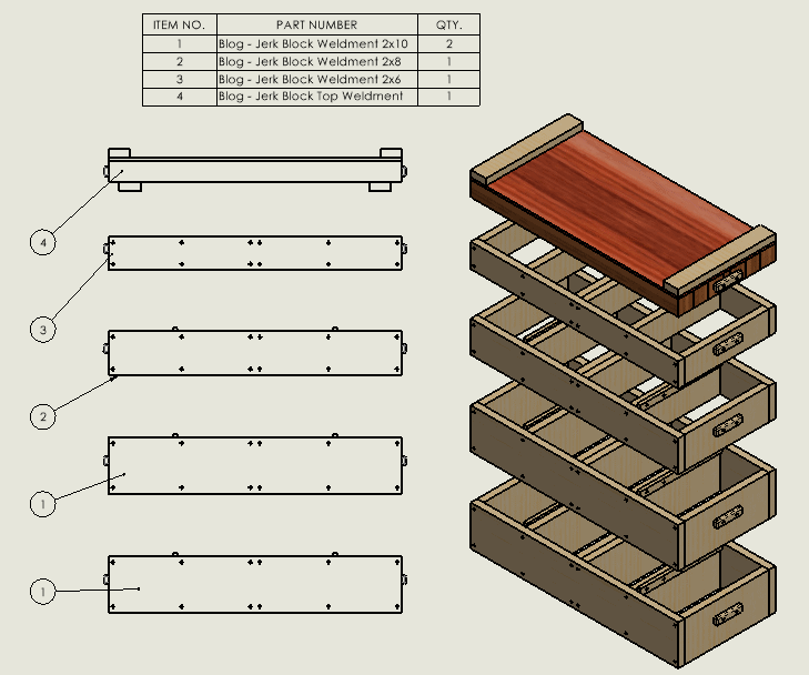
The drawing BOM for the assembly does not look much different. With each section being its own part file instead of configuration, I can be more specific with my naming convention.
Weldments set-up time was a little bit longer because I had to make the weldment profiles, but I can always use those for my next project. On the other hand, the amount of useful detail that I can get from this method far exceeds the small amount of time I had to spend making the profiles. My drawing is much simpler, and I could detail each body if I needed to, so that is not a limitation. Easily seeing my cut-list and lengths without needing a detailed drawing of each body or part can help speed up your drawing time, but this will depend on the facility. A cut-list gives me a nice readable table that makes setting up my stops a lot easier and I can sort my cut-list for length of cut or by description or using them both in combination. It really depends on how your shop is set up and what might be the best method for your fabricators. Having all that information on one page is far superior to looking at multiple pages of part drawings.
I wanted to use the same model to help you understand the differences in just modeling methods. Bottom up gave me a good BOM, but I must hunt for each piece for the drawings, and it still lacked in a cut-list. Muti-body gave me more flexibility with configurations, and I did not have to keep individual part files in order. Again, I did not get an easy-to-read cut-list. Using weldments gave me the nice multi-body design approach, I was able to use different part files for my assembly BOM, and I get a much-welcomed cut-list.
Craig Maurer
Elite Applications Engineer
Computer Aided Technology