SOLIDWORKS Flow Simulation Tutorial: Fluid Flow Problems
Testing fluid flow problems used to be a fairly complicated and difficult process to execute. With the advent of technology, you can now run fluid flow problems virtually. Computational Fluid Dynamics (CFD) has been around for the past 30 years, and it has become even more user-friendly and powerful than it was 30 years ago.
One of the most common questions I hear from users new to CFD is how do I get started? In this SOLIDWORKS Flow Simulation tutorial, I am laying out how to prepare a model for a fluid flow problem. Let’s get started.
What is SOLIDWORKS Flow Simulation?
SOLIDWORKS Flow Simulation is an intuitive Computational Fluid Dynamics (CFD) solution embedded within SOLIDWORKS 3D CAD that enables you to quickly and easily simulate liquid and gas flow through and around your designs to calculate product performance and capabilities. Powered by fast and accurate solvers, SOLIDWORKS Flow Simulation enables you to simulate numerous flow scenarios intuitively while you design. SOLIDWORKS Flow Simulation shortens time to market by saving time and effort searching for the optimum design.
What are the two different study types in SOLIDWORKS Flow Simulation?
Within SOLIDWORKS Flow Simulation users have the ability to solve either external flow or internal flow studies. External flow studies concerns flows not bounded by outer surfaces, but rather only by the fluid domain boundaries. In this case, the solid part is surrounded by the flow, this type of analysis is most commonly associated with aerodynamic studies. Internal flow studies concern flow bounded by outer solid surfaces. In this case, the fluid only circulates on the interior of your part, this type of analysis is most commonly associated with pipe or valve studies.
It is important to understand the two different study types in order to select the appropriate study for your problem. If you select the wrong study type it may prevent you from solving your problem or solving it efficiently.
How to prepare a butterfly valve for internal flow
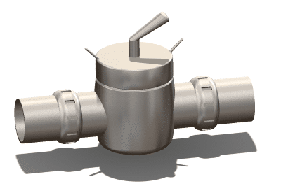
In this part of our Flow Simulation tutorial, the first task for beginning a project is to determine what type of flow study you need to conduct. For a butterfly valve, we want to monitor the fluid effect through the valve – not over the valve.
Therefore, as we are solely concerned with the fluid flow on the interior of the valve, we need to set up an internal flow study within SOLIDWORKS Flow Simulation. Prior to doing that we need to prepare the model. The first thing you should do for any SOLIDWORKS Flow Simulation project is to check the geometry for internal flow, this will determine if your model is watertight. If a model is not watertight, it is indicating that some portion of your model is exposed to the open fluid surrounding your part, and therefore, will need to be closed prior to beginning a Flow Simulation project.
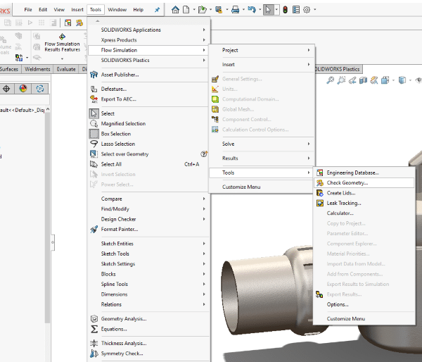
The check geometry option is found under the main Tools Menu > Flow Simulation > Check Geometry.
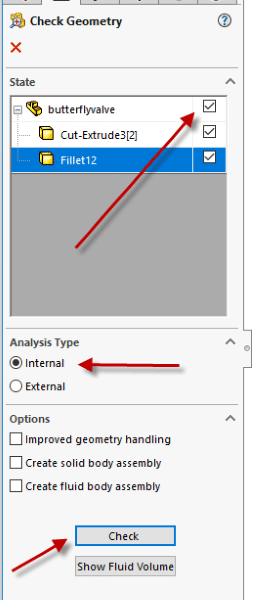
Once we open up the check geometry tool, we can select all applicable parts that we wish to check, in this case, we will use all parts of this valve assembly. We will then select an internal analysis under the analysis type and then select check. This will then run through the check option and determine if the model is watertight and ready to run a Flow Simulation project.
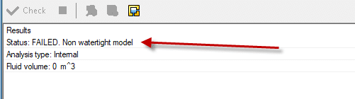
After completion of the check geometry tool, it indicates that the valve failed and that the model is not watertight. This indicates to the user that you need to close any openings in your model. If we look at the butterfly valve, we notice that there are two openings on each of the pipe ends. Therefore, we need to close these openings.
One of the great features of SOLIDWORKS Flow Simulation is the productivity tool called the lid tool that will automatically close openings on planar faces. Since both of the openings are on planar faces, we can utilize this tool.
Please note that if you have non-planar faces, you would just need to go back to the SOLIDWORKS CAD model and close the openings within SOLIDWORKS CAD.
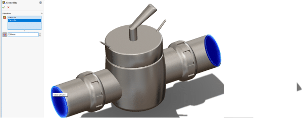
The lid tool is found under the main Tools Menu > Flow Simulation > Tools > Create Lids. Once we open the Lid productivity tool, all we need to do is click on the faces we wish to close and to specify the thickness of the lid. Once we have all faces and thickness, hit the green checkmark and the lids will be automatically created.
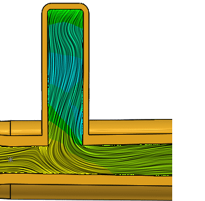
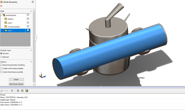
Since we have closed the openings, we can now go back and check the geometry to make sure the valve is watertight. Upon doing this, we see that adding the lids made the model watertight and that the geometry passed. If the model passes the check geometry tool, you can show the fluid domain by hitting show fluid volume. This will illustrate everything in your internal flow that will be modeled as a fluid, the fluid is shown in blue below.
At this point, the butterfly valve is successfully prepped for an internal flow study, and you can now apply your boundary conditions and solve the project.
I hope you enjoyed this SOLIDWORKS Flow Simulation tutorial. For more information regarding SOLIDWORKS Flow Simulation or if you have an interest in talking more about how Flow Simulation can help your fluid dynamics, please contact us.
Related Articles
Top New Features in SOLIDWORKS 2018 Flow Simulation
What’s New in SOLIDWORKS Simulation 2018
How to Deal with Fixture Warnings in SOLIDWORKS Simulation Standard
About the Author
 Drew Buchanan earned a BS in Mechanical Engineering from the University of Pittsburgh, and an MS in Mechanical Engineering from Villanova University. He has been working with Computer-Aided Engineering (CAE) tools since the mid-2000s when he was an engineering co-op with Siemens Power Generation. Upon graduation, Drew worked in the Energy industry for six years working as a design and analysis engineer for design and analysis applications. He joined Fisher Unitech in 2015.