SOLIDWORKS: Modeling Twisted Wires
SOLIDWORKS has some exceptional tools for technical communication. We have photo-rendering with SOLIDWORKS Visualize, product documentation with SOLIDWORKS Composer, and even eDrawings to generate and share an easily viewable file. With these tools, your ability to communicate is dependent on how accurately your parts were modeled. If you want very realistic results, you may consider modeling the finer details in your designs. This would include features like threads, decals, and individual wires. Here, we will look at an easy way to model a twisted pair of wires.
Representing wires and cables in SW is commonly done with a sweep feature. You can easily determine wire length and the routing path by doing a single swept-boss feature using a circular profile. The wire routing tools within SOLIDWORKS Routing use this approach. With this simple sweep method, the design information for the wires is there, but it lacks the extra detail to best communicate the design to others.
In many designs, we use twisted wires to keep them together and neatly arranged. Modeling the wires in a realistic, twisted arrangement will add much needed clarity to photo renderings, drawings, and product instructions. Luckily, this is pretty easy to do in SOLIDWORKS.
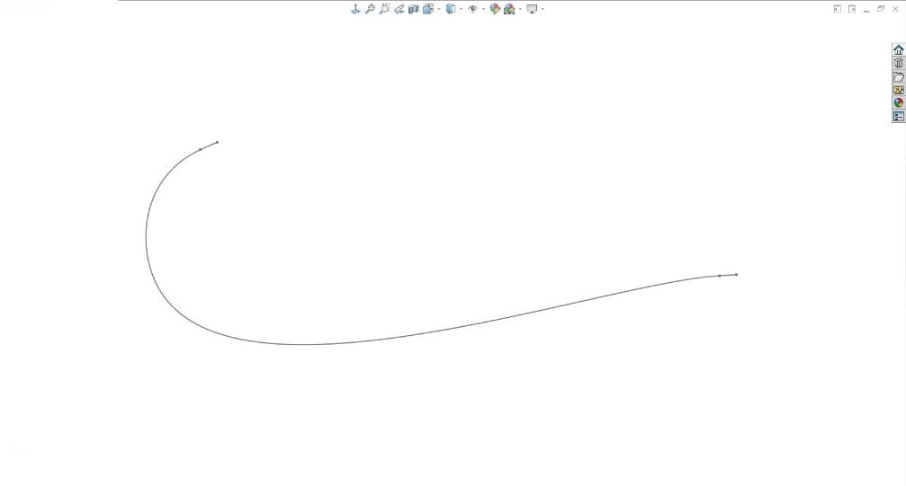
First, you need to create the sweep path. This will most likely be a 3D sketch containing a Spline.
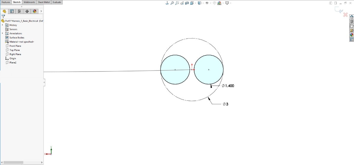
Next, for the profile, sketch the two circles representing the wire diameters.
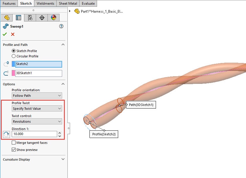
Then, create the sweep feature. You will need to expand the OPTIONS and define “Profile Twist” by the number of revolutions. This will create the two wires as individual solid bodies.
Finally, you can adjust the solid body appearances to match the wire colors.
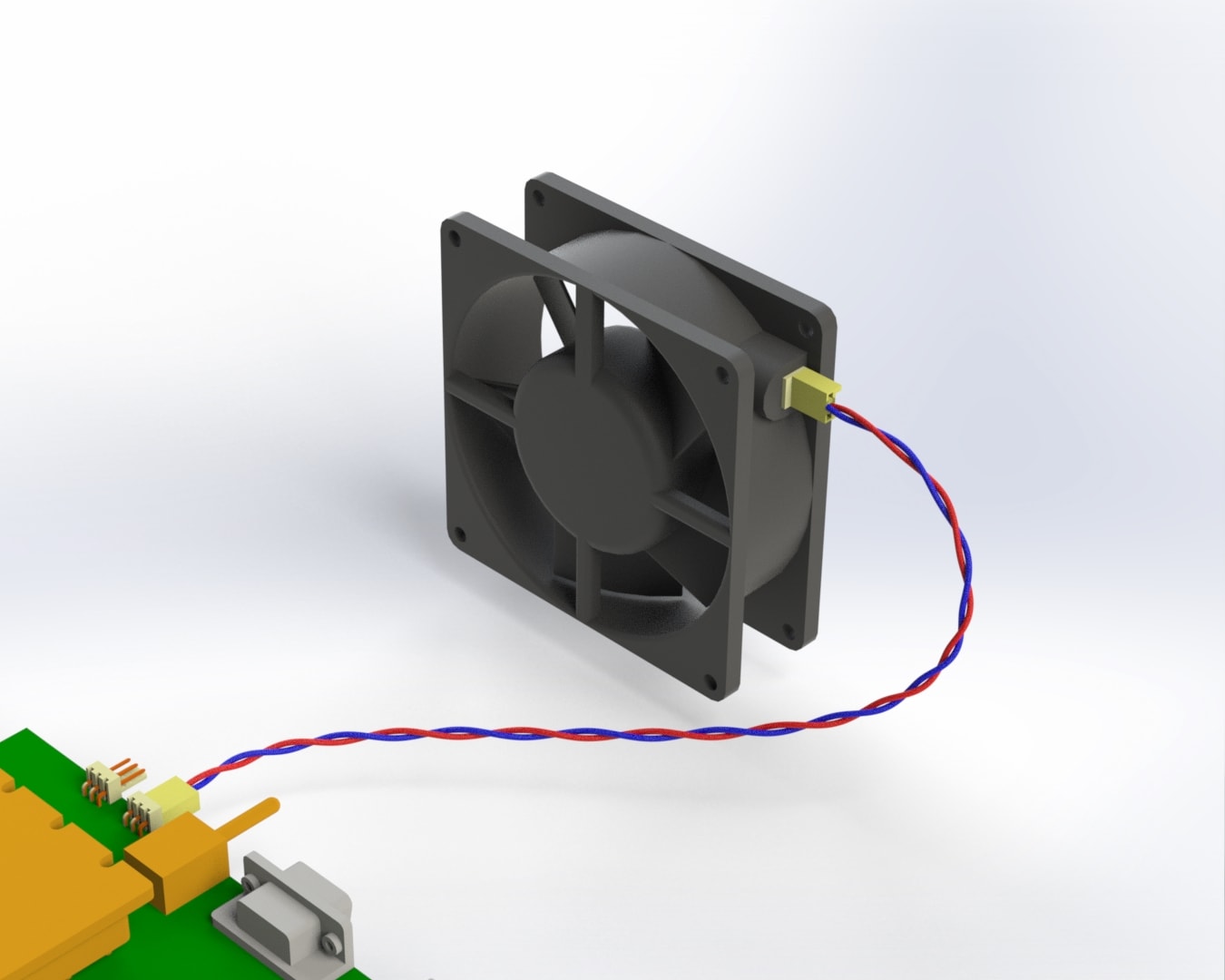
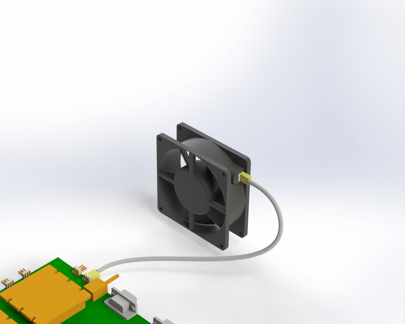
This image is much better for showing how the actual product will look.
In this quick example, we used the twist along path setting to create the twisted wires in SOLIDWORKS. This same technique works great for creating threads and springs too! Check out this blog article for an example of creating a bent spring: https://www.cati.com/blog/2011/06/bent-spring/
Greg Buter
Application Engineer
Computer Aided Technology, LLC