How to Create SOLIDWORKS Multibody Parts Using “Hybrid” Sketching
 Over the years I’ve had many opportunities to use SOLIDWORKS for different projects either for work, home, hobbies, teaching, and more. Working in the industry that I’m in you also tend to observe several habits for better or worse regarding design strategies. One habit that seems to be very consistent, is that people don’t seem to like 3D sketching.
Of course, saying people don’t “like” 3D sketching is one of the biggest understatements of all time. It’s kind of like saying that the Ford Pinto wasn’t an “ideal” racecar. No, the truth of the matter is that people seem to fear and loathe 3D sketching, to the point that they’d rather find any other way to get their design done. Let’s change that. In order to help spread the word, I presented this at my SOLIDWORKS World 2018 breakout session, so if you weren’t able to make it to the last event then you’re in luck. Let’s take a look at what you missed.
This blog is going to cover what I like to call “Hybrid Sketching”. Now, before you get all excited, thinking that you’re about to get a voucher for a Toyota Prius, please understand that “Hybrid Sketching” isn’t a feature in SOLIDWORKS, it’s a specific method or strategy that I’m giving a seemingly pretty name to.
Hybrid Sketching involves designing and creating using 2D and 3D sketching together in harmony. Using a combination of reference geometry and relations to create the result we need. This blog is going to cover the following:
- – Using 2D/3D sketches together to build a SOLIDWORKS multibody part
- – The Weldment feature to keep them separated
- – Sketch Relations to entity cohesion
- – Use reference geometry to place sketches
- – Create, save, and insert sketch blocks
- – Clean up components with the Split Tool
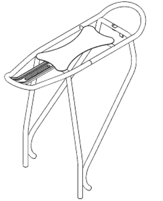
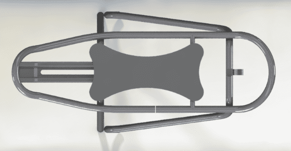
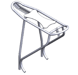 Today we’ll create a model of a bike rack that mounts over the rear wheel of a bicycle. This is a curious piece of geometry because it can be completed a number of different ways. However, the way we’re going to build this model is very specific. We’ll construct this geometry as a multi-body part, specifically using 2D/3D sketches, as well as blocks and curves. Furthermore, we’ll control this part using a layout sketch that will tie into the constraints for everything else.
The stages of the process are as follows:
- Create a Layout Sketch
- Combine with a 3D sketch for the first body
- Use reference geometry to map the support legs
- Create curves to bend the supports in two directions
- Consider “Design Intent” for managing relations to align profiles properly with their paths
- Build blocks to speed up the creation of custom profiles
- Trim and configure our results
When dealing with a multi-body part it’s easy to lose organization of features and the scope of what geometry might be affected. As such, it’s good practice to apply the “Weldment” feature to a part before anything else to ensure we keep the format we want.
The Weldment feature affords us these luxuries:
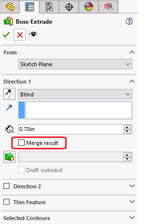
- – Activates the multibody environment by clearing the Merge result checkbox in the Property Managers of features that add material.
- – Organizes all bodies in the “Cut List”.
- – Temporarily disabling “Update Automatically” keeps rebuilds speedy.
 Since we can assume that these bodies will be welded together, we want to make sure that the bodies are separate and organized for easy access. Disabling “Update Automatically” for the cut list can be handled in the “Weldment” section in the Document setting tab in System Options. With the Weldment feature applied, I can now rest assured that all solid bodies I create will, by default, be individual bodies.
The first task of creating our bike rack will involve making a “Base” sketch or layout. This 2D sketch is the bones of what will become our full model. The sketch will define the general shape of the rack and allow for quick adjustments to the size and width of our downstream geometry.
The justification for a base sketch:
- – A base sketch allows flexible control and redundancy
- – Easy location for quick changes
- – Read platform for reference geometry
- – Always pay attention to relations and consider your design intent
- – Use symmetry when it’s necessary
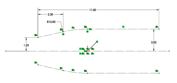
Since this part is symmetrical along the longitudinal axis, it makes sense to sketch the centerline, upper half, then dimension and add relations to the upper half. Afterward, we can then mirror the entities to the bottom. The symmetry relation takes care of the rest. Once the sketch is exited, I like to create my own ISO views to give me just the right level of magnification I want.
I know that the front and rear of this rack are angled upward, so I’m going to need some kind of reference geometry to place my sketches on; before I even continue to sketch the rack body, I’m going to use the endpoints of my base sketch to create two angled planes on both ends of the sketch. I’ll incorporate these planes in my 3D sketch to hold the arches that will make the front and the rear end of my rack.
Note: Get in the habit of naming your features, they make for quick references and are easy to find in the live filter.
Once my reference planes are created I’ll name them in the feature tree so that they’re easy to reference downstream. Next, I’ll start a 3D sketch.
The only difference between a 2D sketch and a 3D sketch is that the latter doesn’t exist on a planar surface. For now, that’s completely okay because we’re simply going to borrow the sketch entities from the “Base Sketch” by selecting the “Base Sketch” and using “Convert Entities” to bring it into our 3D sketch. Once the sketch is converted into our sketch space, we can utilize those beautifully angled planes that we created.
By double clicking on either plane while in the 3D sketch, we can activate the plane for sketching on. A simple 3-point arc will allow us to connect our endpoints on the converted base sketch entities and making the center points coincident to the centerline, we have an angled front and rear end for our rack. However, we’re not done yet. Since this part will be welded, we’ll need to place a break in this path using “Split Entities” and place a horizontal line for a support that will be placed on the rack body. I personally don’t like to see split faces on my geometry, so before I sweep a body I always like to convert my path to splines using ‘Fit Spline”. I’ll then right click on a line in the path, choose “Select Chain”, click “Fit Spline”, uncheck “Close Loop”, and click the green check.
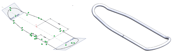
Once swept we get a nice clean continuous single piece of geometry. In summary:
- – Used “Convert Entities” to reference base sketch
- – Place arcs at angled planes with “On Plane” relation, and snap center points to x-axis
- – “Split Entities” allows a break for material weld
- – “Fit Spline” trades a smooth spline for segmented lines for smooth swept body
- – Very few dimensions needed
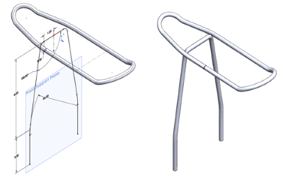
The front support legs are just a simple 2D sketch that lives on a plane that’s offset from the “Right” plane. I’ll do a rough sketch first, add height dimension, sketch fillets, and then finally dimension to key points of the rack body sketch. This allows associativity for my part downstream if I need to make changes. The same rules apply once the entities are sketched. I’ll use “Fit Spline” to get the clean faces that I want before sweeping the path.
Key points for the front support legs are as follows:
- – Sketch first, then dimension
- – Unless there are fillets, then dimension to center points after placing fillets
- – Use mirror sketch for symmetry
- – Again, “Fit Spline” to ensure a smooth body
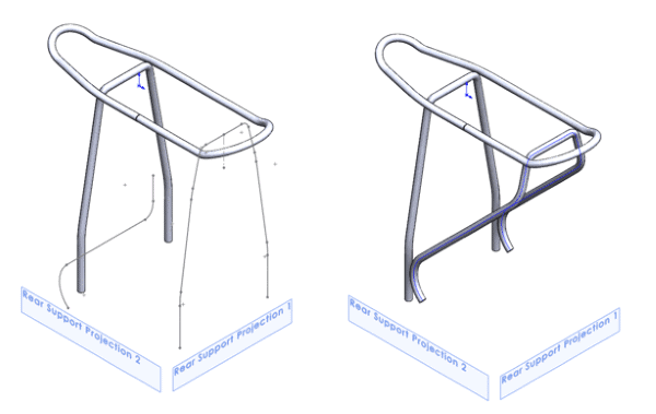
The curveball (pun intended) comes when we get to the rear support legs. You see, those legs actually bend in two directions, so this actually complicates matters.
I could get more data and create a complex 3D sketched spline or I could use a feature meant specifically for this type of situation. The feature I”m talking about is called “Project Curve”. Project Curve allows me to make multiple sketches on multiple planar surfaces and project them in a linear intersection path. It then makes a curve from where the sketches intersect. This allows me to get the exact curve that I need for my rear support leg.
For the rear support legs, I have a very clear angled path on the side, and a tapered path from the rear. This means that the legs are bent in two directions. The first sketch will be to the side of the rack body, while the other will be to the rear. The same process is applied as before, with dimensioning, sketched fillets, and applying a Fit Spline.
Curves allow up to make precise entities in a very short time.
- – Sketch planes are offset proper distance in two directions
- – This is due to the fact that the rear support is bent in two directions
- – Leg paths are sketched, mirrored, and converted into splines
- – “Project Curve” projects both sketches in a linear path and keeps the intersection as a 3D curve
- – Once the curve is complete it can be swept for the new body
Now that most of the time-consuming features are taken care of we now start to focus on the smaller details and gaining a little more efficiency of our time. While most of this rack is completed, there are still several fixtures to add. One of such is the support for the rack body. This support will add structural support to the rack body.
Fortunately, we already prepared for this feature by already sketching a reference line for it back when we created the sketch for the rack body. Now, all we need to do is start a sketch on the Front plane, draw a circle and place a dimension and a couple of relations. Using the orientation, the body that this support creates will help support the rack seat that will be welded to the top of the rack body.
- – Using reference geometry from an earlier sketch, we can place a profile for a simple extrusion to create a brace
- – This piece will also double as a mount for the racks seat
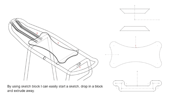
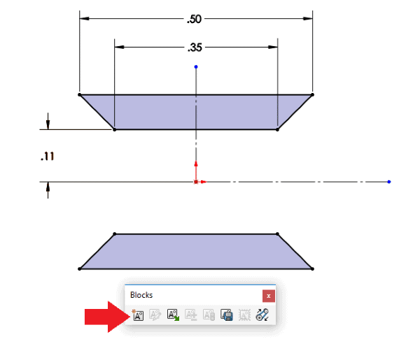
Up until now, we’ve been drawing our own profiles for bodies that we’ve been extruding or sweeping. While this is the way of the world, what happens when I need to be faster? Maybe I have parts that are used often and have been standardized. If that’s the case then I want to be able to access and insert standard profiles as quickly as possible. This brings us to blocks.
With Sketch Blocks I can:
- – Quickly add profiles for sweeps, extrusions, cuts, and more
- – Place profiles wherever I need them to be with ease
- – Save, library, edit, and insert profiles into any sketch plane or file
- – Have less worry about the quality of my sketch
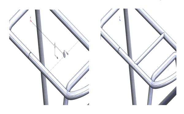
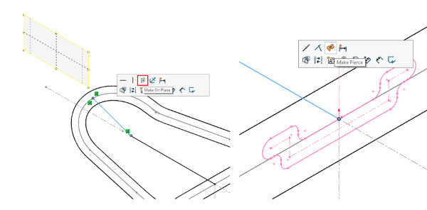
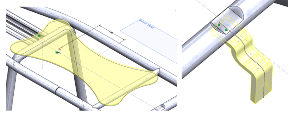
For the adjustment rail, I’ll need a path to sweep the profile along. I’ll start a 3D sketch and click on the line tool. Once the line tool is selected you’ll notice that cursor shows an indicator as to what axis or planar direction you’re pointing.
It’ll be one of following: XY, YZ, or ZX
These directions can be cycled by pressing the “Tab” key on your keyboard. By cycling the Tab key I can set my line to follow the XY plane, and set up the sweep path for my adjustment rail profile. If I select the Front plane and my line, I can even set an “On Plane” relation attaching my line to that default plane further ensuring that my entities will stay where I need them to be. I’ll also use a “Pierce” relation to ensure that my sweep path intersects the driving sketch of the rack body so that my sweep will end cleanly into another body.
I can use a sketch block for the profile of the adjustment rail that allows for better fitment of my rack. This is loaded from a library or folder, and with one click and a simple relation, the sketch is fully defined for use.
The efficiency of Blocks:
- – Blocks allow us to standardize sketch entities or profiles for quick use
- – Decreases chance of bad geometry by grouping and locking entities together
- – Allow for quick placement with minimal relations or dimension
Last Fixtures:
- – Once again, by using blocks, I am able to place these sketches quickly and precisely
- – Relations and Dimensions are minimal due to the block entities being grouped together holding their positions
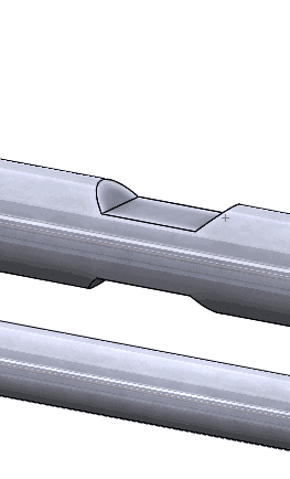
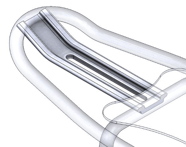
Removing extra geometry and adding a configuration:
- – Due to the way we orientated our “Adjustment Rail” feature, we have some geometry that is overlapping other bodies
- – This would produce parts that are not correct for assembly
- – We can create a configuration that can show the difference in part geometry
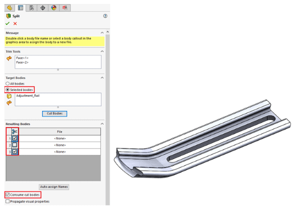
The Split Feature saves the day!
The Split Feature allows me to remove overlapping geometry specific to a select group. This allows me to get the exact shape I would need for assembly of the “Adjustment Rail”.
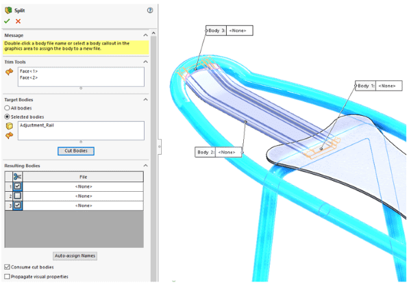
Once the correct geometry is chosen I can choose what to keep, and what to discard. Checking the “Consume Cut Bodies” checkbox allows the scrap geometry to be deleted. Once complete, configurations can be created to hold other features like holes or shells for the bodies.
That completes this blog on SOLIDWORKS Multibody parts using “Hybrid Sketching”, I hope that you’ve been able to comprehend that both 2D and 3D sketching can co-exist in a design, and they actually work really well together. 3D sketching isn’t the monster it’s made out to be, it simply just takes a little extra care and awareness when placing entities where you need them to be.
More Presentations from SOLIDWORKS World 2018
Introduction to SOLIDWORKS Mold Tools
Simplify Your SOLIDWORKS Custom Property Input with the Custom Properties Tab
How to Use SOLIDWORKS Treehouse and Templates to Create Assemblies Faster
About the Author
 Jay-Shan Jackson has been with the Fisher Unitech family since 2017 as a Customer Support Engineer and is based out of the Fisher Unitech office in Cincinnati, Ohio. Jay-Shan is a Certified SOLIDWORKS Expert with an expertise in mechanical design.