The Holster Project Springs into Action: Design to Manufacturing Series (Part 8)
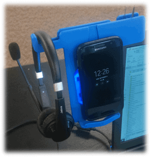 Earlier in our Design to Manufacturing blog series, we introduced The Holster Project, a design concept for our headset and cellphone stand. With the use of additive manufacturing technologies like 3D printing and 3D scanning, as well as a variety of tools found in SOLIDWORKS 3D CAD software, we were able to produce a prototype and test how well our design would work. Unfortunately, our design has had its share of challenges. For instance, when we placed it on a laptop monitor without any attachments, it immediately fell off so we designed a spring clip to fasten the stand to the monitor. The spring clips would account for different thicknesses in monitor brands and styles and would also apply pressure to hold the stand in place. However, they didn’t work as well as we hoped and as a result, our prototype ended up in pieces.
Before investing time into a redesign that would require a clamping mechanism, we would need a prototype, feasibility study, and a mock-up model just to see if this would work. As I started to feel the pressure of our deadline on my shoulders, I took one last look around my desk. As luck would have it, the solution to my problem was right under my nose: a binder clip. It’s the perfect size, but it is the perfect strength?
Part 1 | Part 2 | Part 3 | Part 4 | Part 5 | Part 6 | Part 7
There’s nothing that a Dremel and some duct tape can’t fix (MacGyver would be proud). As you can see in the video above, it isn’t pretty – but hey, it holds.
The new design is comprised of a hinged clamp off the back wall of the stand and includes a hinged stabilizing foot. We needed to figure out the spring force required to counteract the weight of the phone stand, the cellphone, and the headset, all of which are cantilevered off the side of the laptop monitor. To do this, we set up a Simulation study using SOLIDWORKS Simulation Standard to determine the minimum force needed for the clamp to achieve a stable system.
Bring in SOLIDWORKS Simulation
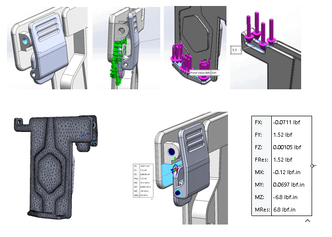
Using SOLIDWORKS Simulation Standard, we specified the appropriate contact conditions to represent the rotational contacts for the hinged assemblies. We specified the fixtures to be in the front and the back faces of the clamp components that would be in contact with the laptop monitor. Next, we specified forces: The first being gravity taking into account the weight of the stand and second being downward force on the phone support shelf representing the weight of the cellphone. Third and finally, we added an additional downward force on the headset support representing the weight of the headset.
We created a preliminary mesh for evaluation and refined it as needed. With our stable system, SOLIDWORKS Simulation Standard calculated and displayed the force values between the fixed clamp faces, which provides the minimum force needed to overcome the phone stand’s reaction forces and moments.
May the force value be with you
The reaction forces provided by our FEA for FX, FY, FZ, & FRes showed the highest force value to overcome was 1.52 lbf. Notice that our FY and FRes forces are essentially identical. This tells us that the reaction forces generated in the X and Z directions are negligible. Now that we have a force value of 1.52 lbf we need to source a spring that will work accordingly.
Since our deadline was quickly approaching, we decided to use an off-the-shelf spring (we can always engineer one once we have shown that that the assembly functions properly). Using our 1.5 lbf as our baseline, we could use a torsion spring with a spring rate value of 1.82 in-lb. That is slightly higher than our calculated 1.52 lbf minimum lb-in value.
The trick with torsion springs is that 1.82 in-lb value is for the Max Torque. So the spring would need to be displaced to the maximum amount in order to achieve 1.82 in-lb. Our spring is a 120-degree Torsion spring so we would need to displace it by 120 degrees to generate 1.82 in-lb. Also, that spring rate of 1.82 in-lb is a unit for Torques/Moments. We will need to convert it to a Force value. With all that said, we knew we would not displace the spring to the full amount, and to account for different sized phones, we decided to add a second spring for good measure.
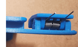
 Once we received our hardware and 3D printed parts it became clear that assembly can possibly make or break a design. On our first attempt, we assembled the prototype with a preloaded spring of about 30 degrees due to some assembly difficulty (Note: The right tools and an extra set of hands solves this, as we’ll see later).
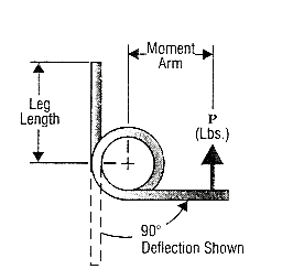
From our calculations, it became obvious that the springs will need to be preloaded more than 30 degrees in order to function properly. The Moment Arm (Leg Length) * P (Max Force) = Max. Torque. So with some rearranging we get (1.82 in-lb)/1.25in = 1.456 lbf. That is the maximum amount of force that the spring can produce. From this we can extrapolate that each degree provides 0.0121333̅ (repeating of course) lbf/Deg {1.456 lbf/ 120 Deg}. This means that we were only producing 2*(0.012133lbf/Deg*30 Deg) = 0.728 lbf. Well it’s pretty easy to see that 0.728 lbf < 1.52 lbf.
 Now we need more force. At 30 degrees of displacement, we are producing about a quarter of the amount of the total force for each of these springs. If we preload the springs more, we will produce more force. If we displace the springs about 90 degrees then they will produce approximately 2*(0.012133lbf/Deg*90 Deg) = 2.184 lbf. 2.184 lbf > 1.52 lbf. The calculations tell us that the springs will work. Thanks to an extra set of hands, we were able to get the assembly together with the springs preloaded about 90 degrees. The Holster securely sits off the side of the laptop monitor, in portrait orientation, and at a comfortable eye level.
By using SOLIDWORKS Simulation to calculate the spring force, the Holster’s engineering challenges have been resolved, we are so excited and relieved! Now to finalize the aesthetic…Stay tuned!
Related Articles
The Top 5 CAD Features in SOLIDWORKS 2020
Get Up to Speed with 3DEXPERIENCE
Is it Time to Give Your SOLIDWORKS Skills a Tune-Up?
About the Authors
 Laura Nickerson is an Application Engineer with Fisher Unitech. She has 17 years of experience in the consumer appliance industry working as an industrial designer and mechanical designer. Laura is detail-oriented, a problem solver, and is listed as co-inventor in over 40 patents.
 James Reeher has a Bachelor of Science in Mechanical Engineering from Cleveland State University and began using Solidworks in 2007. After many years as a Product Development Engineer in the industrial fitting, biomedical device, and LED lighting industries he joined the Fisher Unitech team in 2016. James is very interested in new technology and how different technologies can be applied to one another. As an Application Engineer, he enjoys helping customers learn how to leverage SOLIDWORKS to meet their needs and introduce them to other technologies that can help their business.