Deadpool’s Minor Surface Flaws – Part 1
I’m a fan of Deadpool. I got my first taste of Deadpool when Ryan Reynolds played Wade Wilson in X-Men Origins: Wolverine. I liked his quick wit and general smart aleckery, not to mention his first few scenes were the best parts of the movie (I refuse to remember the scenes where his mouth was sewn shut). After that I went and got my hands on every Deadpool comic I could and cannot wait for the full feature film later this week. To pay homage to the great Merc with a Mouth, I decided I would create a model of his mask to show you some cool SOLIDWORKS surfacing capabilities.
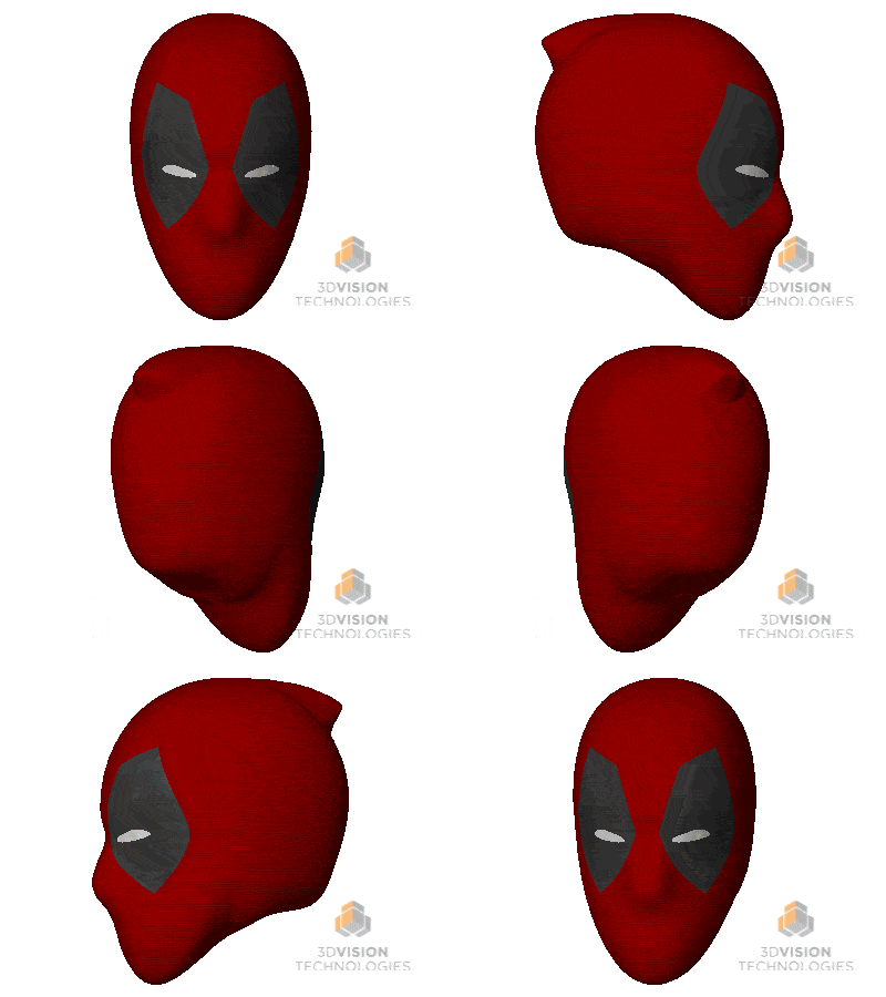
Now if I were really designing this part in the real world I would probably use SOLIDWORKS Industrial Designer (SWID). It’s a great tool that combines subdivision surface modeling and parametric modeling to quickly generate complex geometry. But sometimes, you have to make do with what you have and SOLIDWORKS can absolutely create this type of geometry.
Just for reference this type of model took me a couple hours to make and tweak to get the full shape I wanted whereas SWID could probably do this in less than 30 minutes. My common sense is tingling for another blog post idea…. Anyway, back to the action!
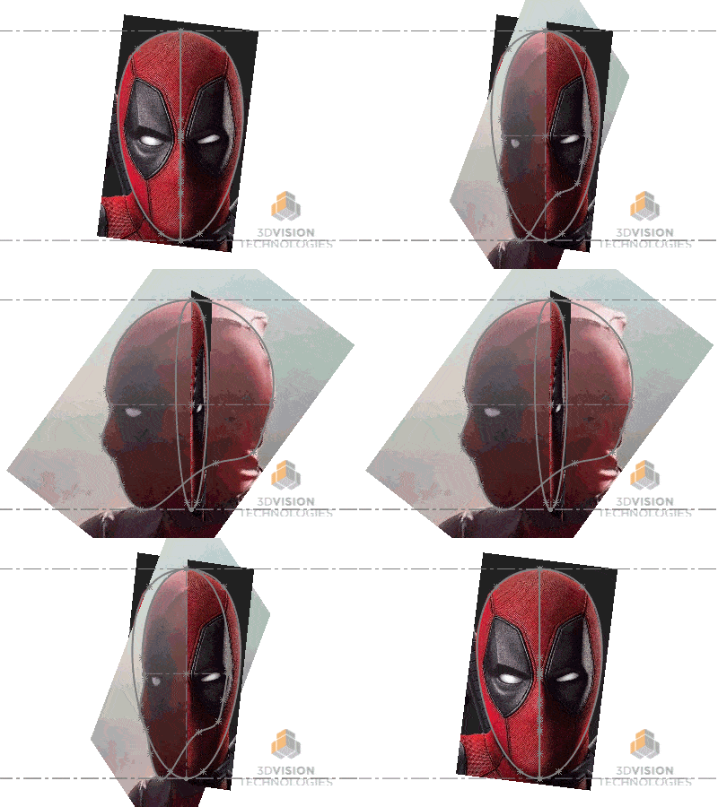
First thing to do is grab some pictures off the internet and put them in sketches for the front and side profile of the head. Then trace out the profiles you want to use in separate sketches. This way you can hide the pictures and not worry about the pictures being in your way all the time.
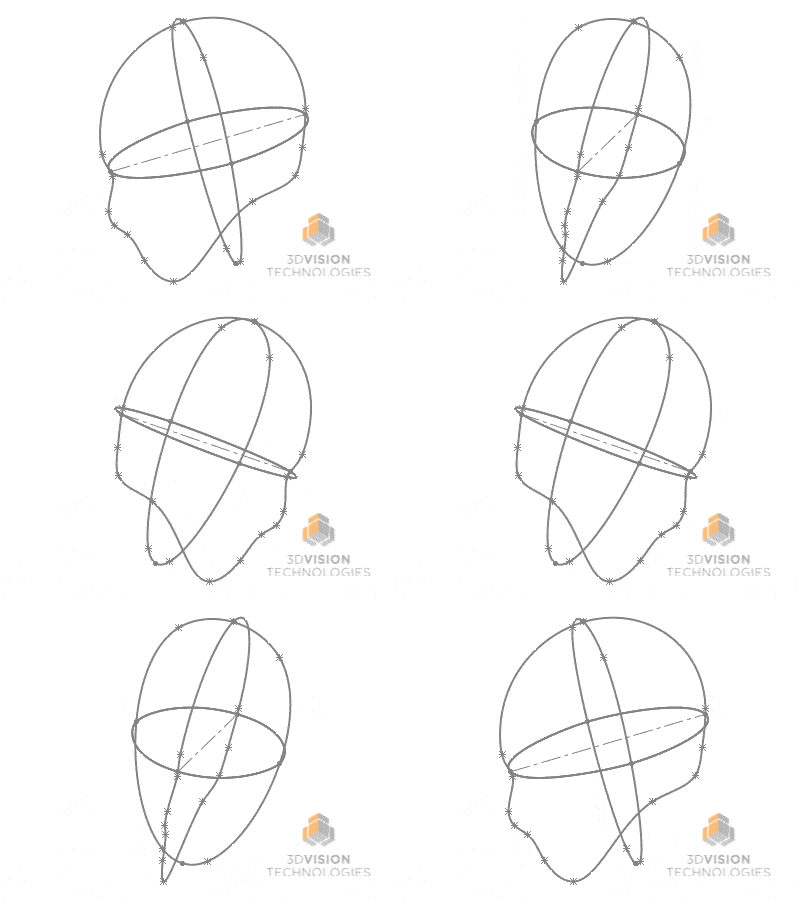
I also added a sketch on the Top Plane to further define the curvature of the head and what I’m left with is three sketches defining the overall shape.
Now I need a plan of attack. I need to break this down into sections and work them one at a time to get my overall shape. Also, since this is a symmetric shape, I can do half the work and mirror it, thank you left brain / right brain! First I’ll create the top front quadrant with a Surface Loft and use the Top Plane sketch as my guide. SPOILER! It won’t work with the sketches I have! SOLIDWORKS needs some help breaking down the sketches into the quadrant I want, maybe someday SOLIDWORKS will link directly to the brain and know what I’m thinking, but for now I need to help it out a little. So I’ll create some additional sketches converting entities, adding in some additional support lines and trimming back what I don’t need to get the following.
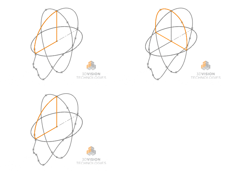
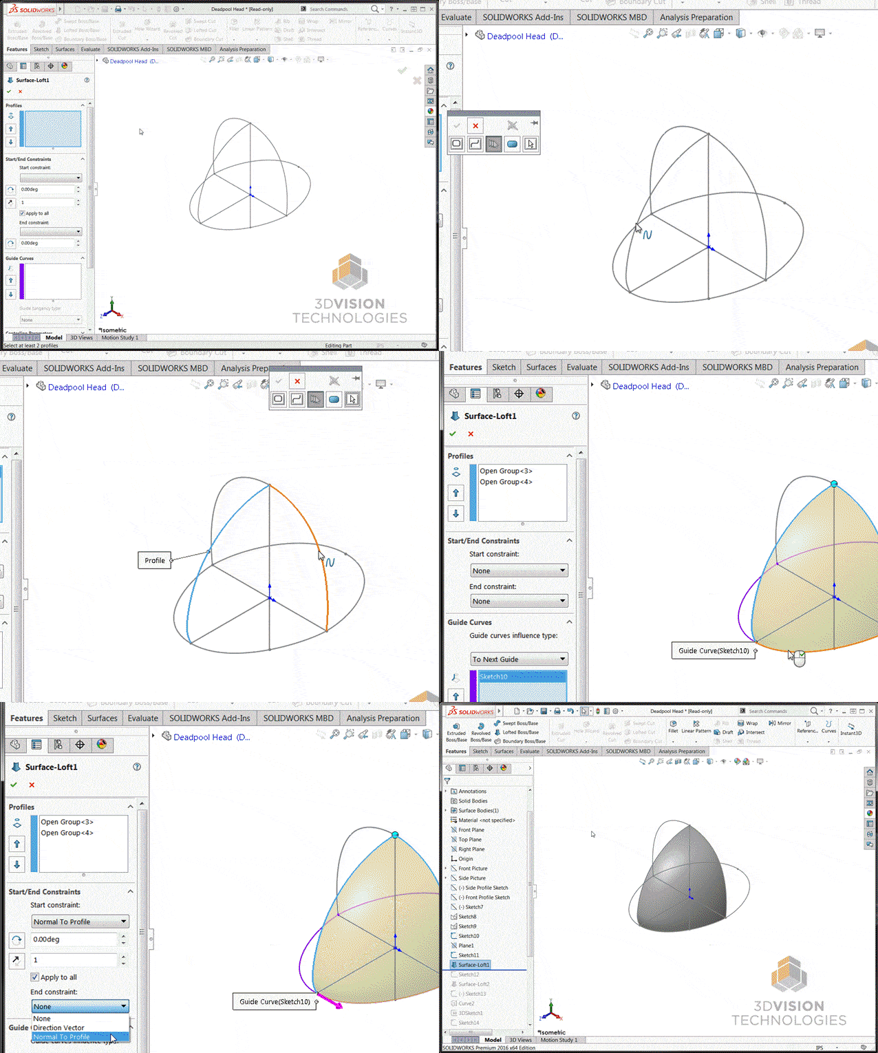
I’ll go ahead and hide the sketches I won’t be using for the loft so I don’t accidently select them and now I’m ready for my first Surface Loft. (Insert > Surface > Loft) I’ll use “Normal to Profile” for both the Start and End constraint so I get a nice smooth transition.
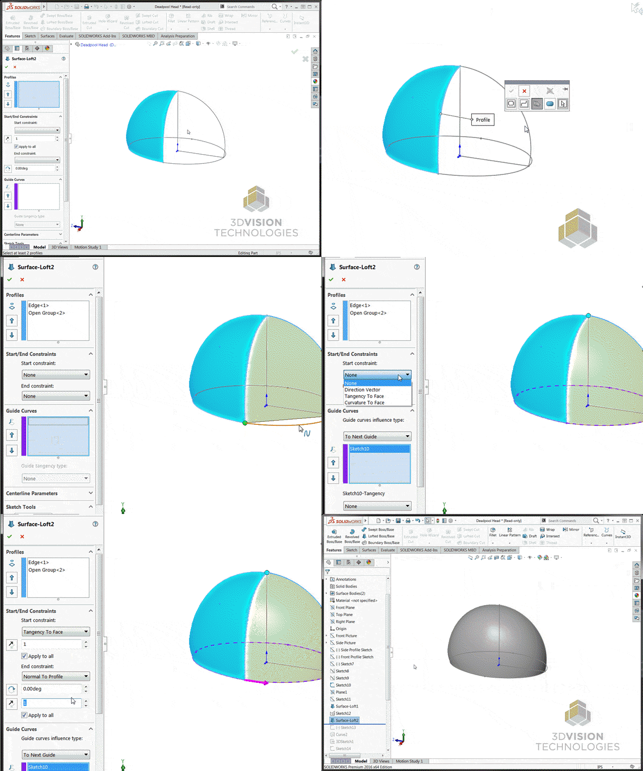
Next step is to add the back half of the head. And to do that I’ll have to create one more converted and trimmed sketch so I get only the geometry I want for the loft. Then to create the back half I can use another Surface Loft similar to what I did before. The only difference here is that I can use the edge of my existing Surface to start.
Now that the easy part is taken care of, I need to get into the more complicated surfaces. Luckily Deadpool, despite constantly talking, found it unnecessary to add any shape to his mouth, so I won’t have to worry about that additional geometry. I will need to get his nose and jaw started, but tune in next time kiddos to see how I tackled that fun challenge!
Deadpool’s Minor Surface Flaws – Part 1
Deadpool’s Minor Surface Flaws – Part 2
Deadpool’s Minor Surface Flaws – Part 3 – THE FINAL SHOWDOWN (ISH?)
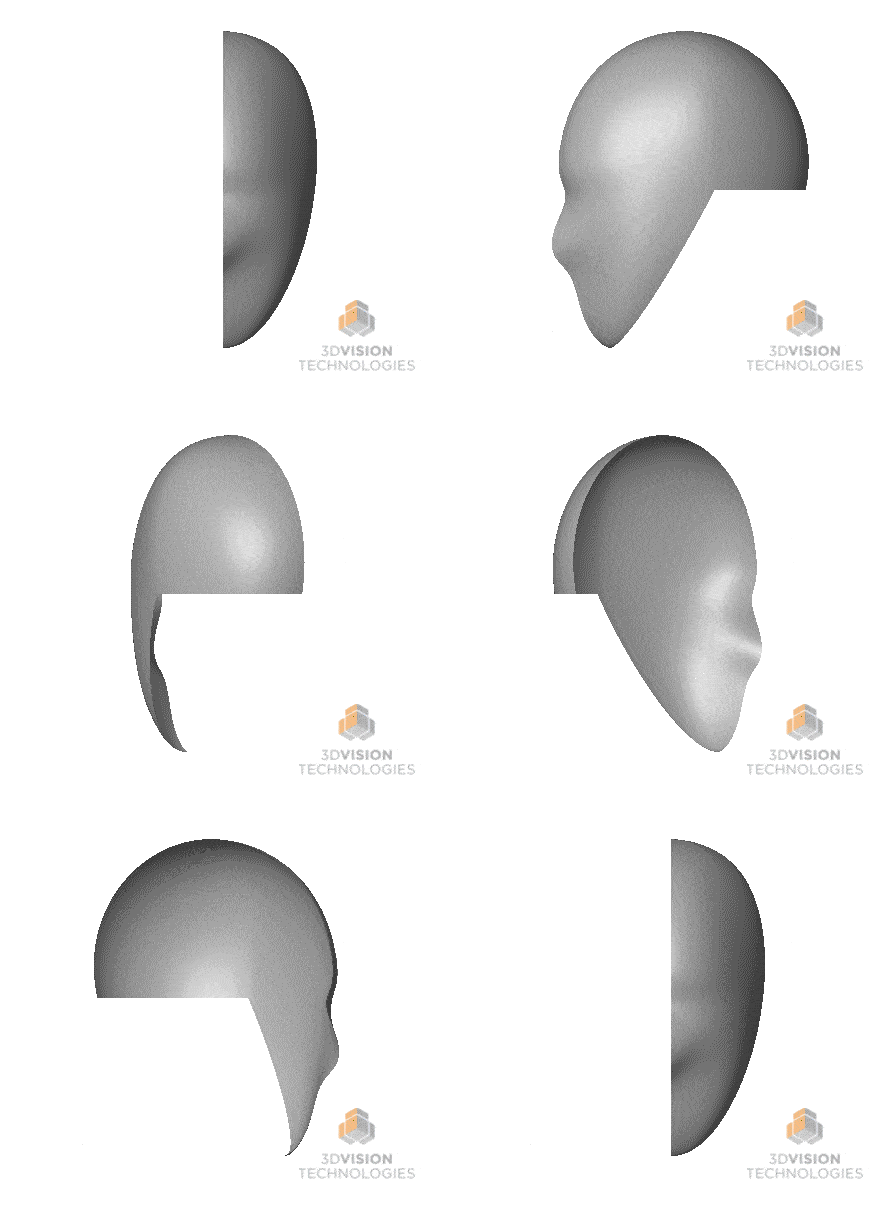
If you have any questions or comments please share down below!
Brandon Nelms
Application Engineer
Computer Aided Technology, Inc

 Blog
Blog