The Right Tool for the Job Part 2: The Single Body Limitation in Sim Xpress
In my last blog, I introduced SOLIDWORKS Simulation Standard and how it is a lot of analysis power for the money. One point that I made is that there are many times when SOLIDWORKS users might be trying to do too much with the free Xpress tools or might not realize what they are missing in a more complete solution like Simulation Standard Professional or Premium. In this blog, I will discuss the single body limitation imposed by Sim Xpress.
Sim Xpress allows only a single body and “fixed” constraints that stop motion on the chosen face in the X, Y, Z directions. The main reason for this limitation is that it prevents users from creating an unstable model by accident. Fix any face in X, Y, Z directions on a single body and you are going to have a stable model. In other words it’s a slam dunk that the solver will able to solve for equilibrium and we can find a solution. This limitation guarantees a solution but limits the areas we can accurately extract stresses from and limits the types of situations we can accurately reproduce.
The Single Body Limitation Caveat:
When running a physical test, such as running an electronics housing on a shaker test, we don’t usually bolt the part directly to the test bed. To more accurately represent the stiffness of the environment we should include supporting components such as brackets. Similar rules apply to structural analysis .
The Repercussions of Fixtures on the Body of Interest:
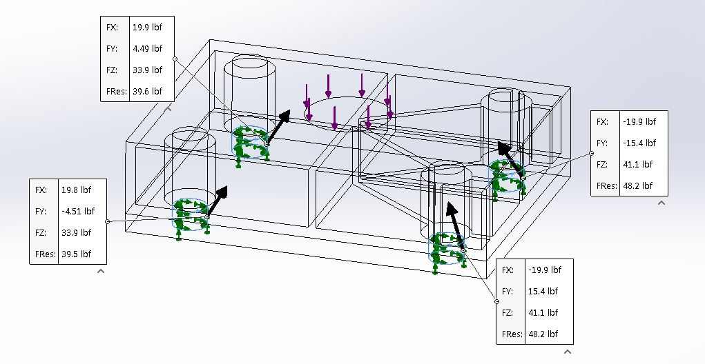
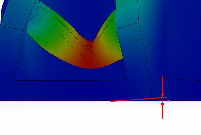
- When we put fixtures on the part of interest we have a less accurate representation of our part interaction with the rest of its environment. Stress follows the path of highest stiffness and supporting bodies could affect the load distribution in the part. In the examples below we have a housing with one side ribbed and the other is gusseted without reinforcements. The iso plot of stress helps us understand the load path.
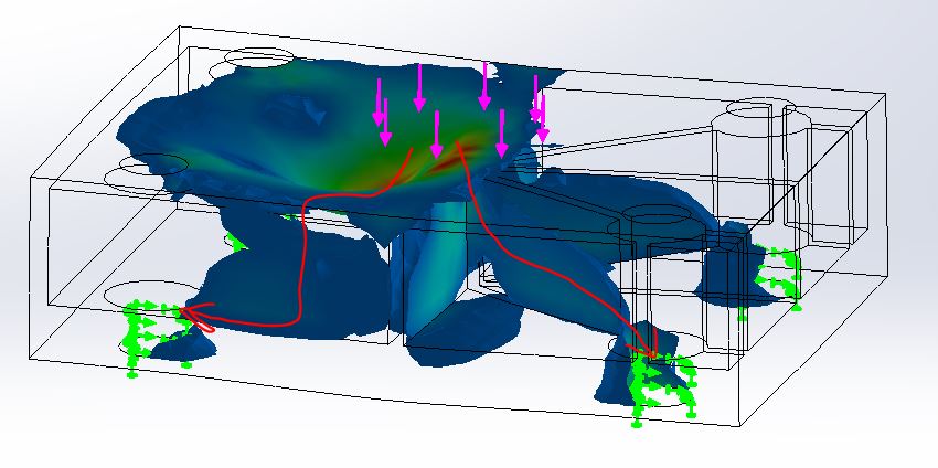
If we inspect the reaction forces we will see that the stiffer side is carrying more load as expected. This is analogous to two springs in parallel. The stiffer spring will carry more of the load, depending on the variation of support stiffness that can affect our base part analysis.
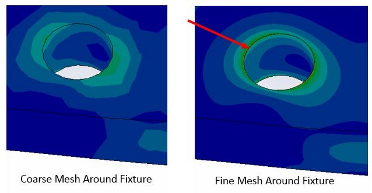
- Stresses at fixtures are always ignored. Why is this? The fixture is infinitely rigid yet the part has some stiffness. This creates a mathematical discontinuity known as a singularity. It sounds fancy but it’s pretty simple and it’s one of the first topics in our CAE205 class introduction to FEA.
In a nutshell, the stresses at our fixture will continue to rise and become more local as we refine the mesh. At a singularity, the stress level is indefinite. Therefore, if our connection points are of interest we need to take the analysis to the next level.
The Next Level Solution:
If we have access to a more complete FEA solution such as SOLIDWORKS Simulation Standard we can investigate our fixture points or interaction with the rest of the assembly in more detail. Starting from the simplest to the most accurate, let’s look at three options:
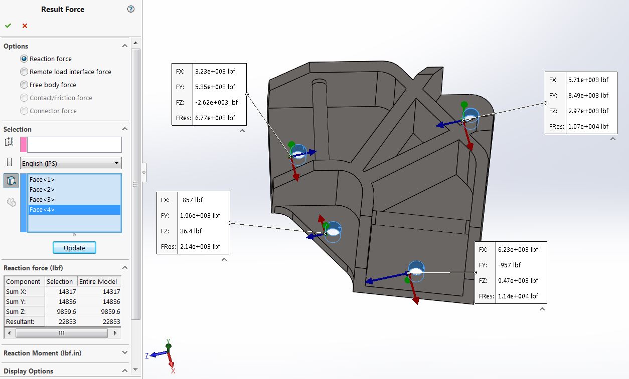
- Extract forces from the fixture and do our own calculations: The simplest quick check to understand our connections might be as simple as extracting the reaction forces from our fixtures and doing our own hand calcs to verify our fastener selection. As part of the results capabilities we can list forces at our fixtures or anywhere in the model.
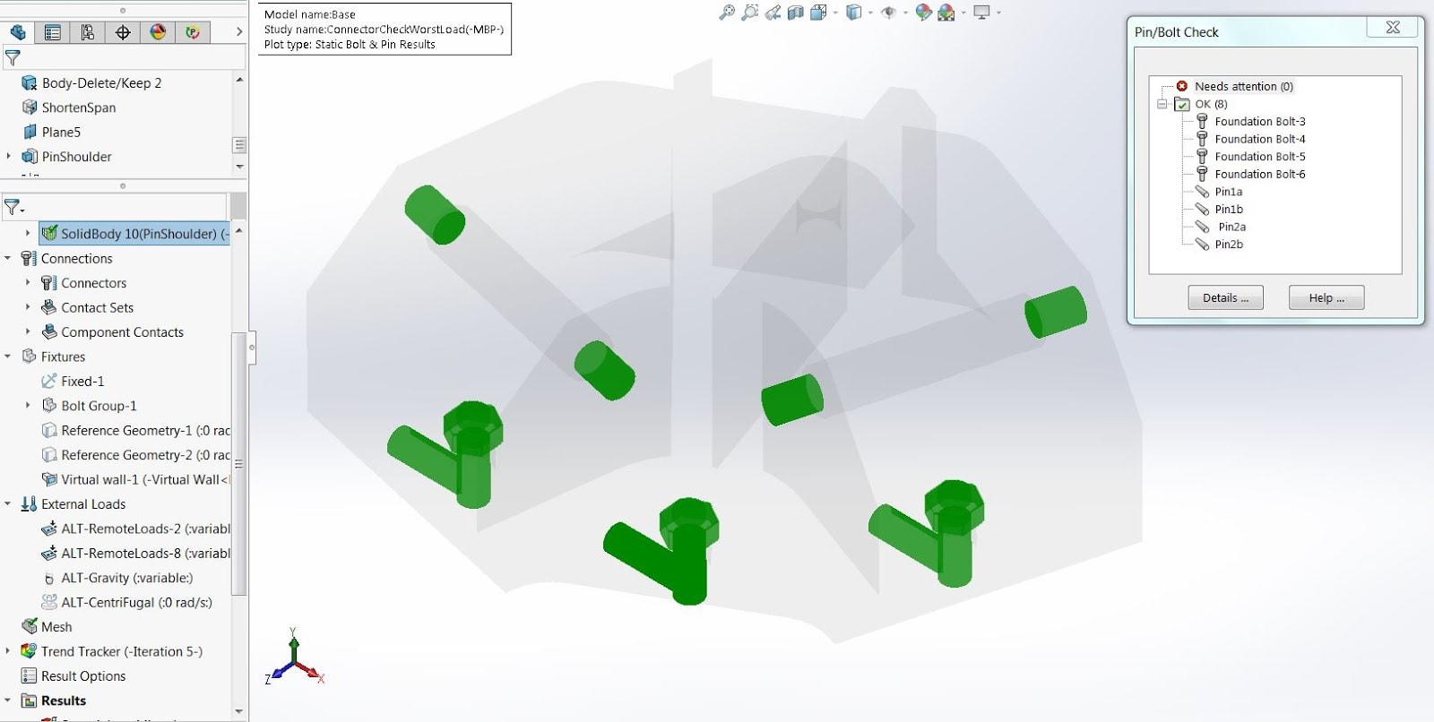
- Use foundation bolts: The next level is to use a foundation bolt combined with a virtual wall contact. This would include the preload from our fasteners as well as allowing the clamped body to lift up but not pass through the virtual floor contact as shown below.
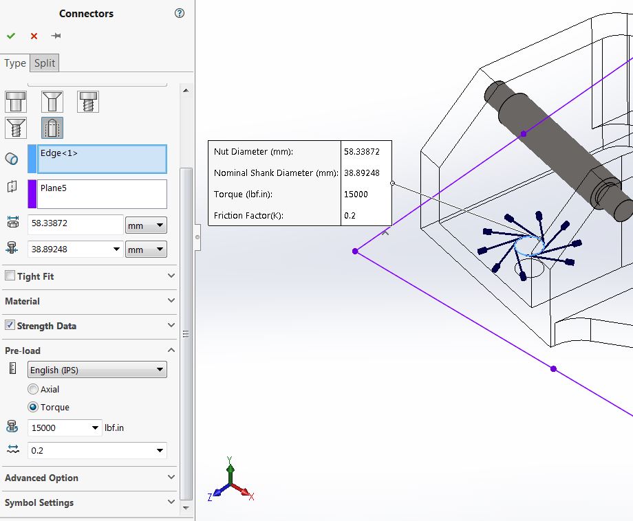
If our base is substantially stiffer than our part, this is an ideal option. We can then use the fasteners, check plots, or extract loads from our fasteners for our own checks. This is the method used in the Introduction to Simulation Standard video where we first used motion to determine forces, ran a simple screening study and then ran more detailed studies on the fasteners:
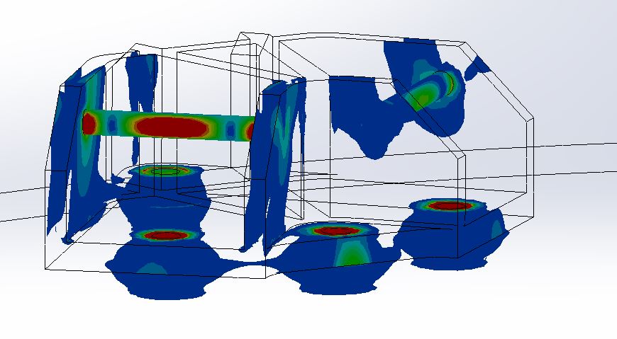
- Model the second body with bolts and contact: This option includes the detail of the bolt model along with the flexibility of the mating part. If the mating part is not significantly stiffer than our part of interest, this is important since it will affect the “load path”. Below is an iso stress plot of our bracket modeled with the base plate. We can not only extract the bolt factors of safety but we have accounted for the stiffness of the supporting bodies.
I hope this blog helps you understand the limitations of the Xpress tools so that we can use them more wisely and recognize when we need to take it to the next level.
In my next post we will discuss the constraint options available in Simulation Standard such as:
- – Remote Loads
- – Fixed Hinges
- – Advanced Fixtures
- – On Cylindrical Faces
- – and more ….
We will compare these options to the single fixed face option in Sim Xpress. Happy Simulating!
Related Articles:
- – Simulation Standard: The Right Tool for the Job
- – The Right Tool for the Job Part 3: Getting Your Fix with Fixtures
About the Author:
David Roccaforte earned a BS and MS in Mechanical Engineering from the University of Michigan-Dearborn. He has been working with Computer-Aided Engineering (CAE) tools since the mid-1990s when he was an engineering coop and later a product engineer with Automotive System Laboratory. Seeing the value that CAE brings to the engineering process inspired him to concentrate on CAE during his graduate studies. While finishing his graduate studies, he worked for Mechanical Dynamics as an engineering intern running vehicle dynamics analysis.
After finishing his graduate studies, David worked in the automotive Industry as an Engineering Analyst with Karmann Technical Development supporting the design of convertible roof systems for North American OEM’s. From there Roccaforte joined MSC Software, one of the top companies in engineering simulation, where he worked as a Senior Application Engineer until he joined Fisher Unitech in 2010.