SOLIDWORKS Designs: Fully Functional Drink Dispenser
 In order to produce high-quality products, designers, engineers, and inventors must have a strategy for a productive design process. There is a myriad of individual methods involved in a personal design process, all employing the use of specialized tools. Today’s technology has wholly revolutionized the design process, offering countless new possibilities for turning dreams into reality.If you had the power to bring your ideas to life, what would you create?
In this blog series, I’m taking you on the journey from idea to working model. Thanks to SOLIDWORKS 3D CAD and 3D printers provided by Fisher Unitech, I will be able to see my design come to life. I will use the multitude of tools of SOLIDWORKS to create a working simulated computer model and the high-quality precision and speed of a Stratasys 3D printer to build my model. I will then program my product to be fully automated. In this blog, I will discuss the design process from a couple of sketches to a working model. Let’s get started!
Ideation
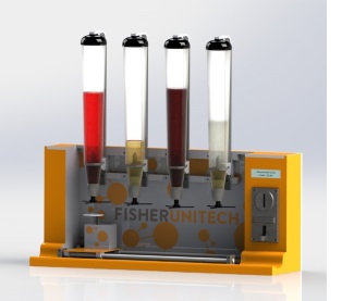
The concept of my design is a fully automated drink dispenser which will house four different beverages that a customer can purchase. After selecting a beverage, the machine will take the glass, move to the correct dispenser, and automatically dispense the beverage. I am programming the device so that when you select a drink, you can see the price and size and the machine will calculate how much each glass will cost.
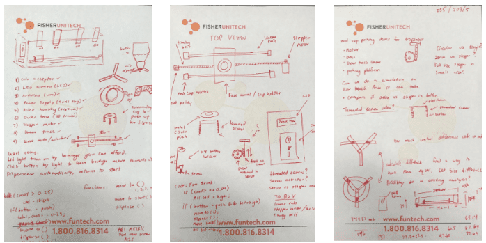
When you think of a good idea, the first step to bring it to life is to start sketching. I had the basic premise of how I wanted to tackle my design, so I made a few sketches.
Planning
After a little research, I decided that I wanted a linear track as the primary moving mechanism for the cup. I found a set of rails online that I based my original dimensions on. I decided to start my design process in SOLIDWORKS with the linear track. The basic premise of the track is that two rails are held in place by supports. Attached to the linear rails are four separate ball bearing bushings that can move freely along the track. These are connected to the top plate, which will be home to the cup.
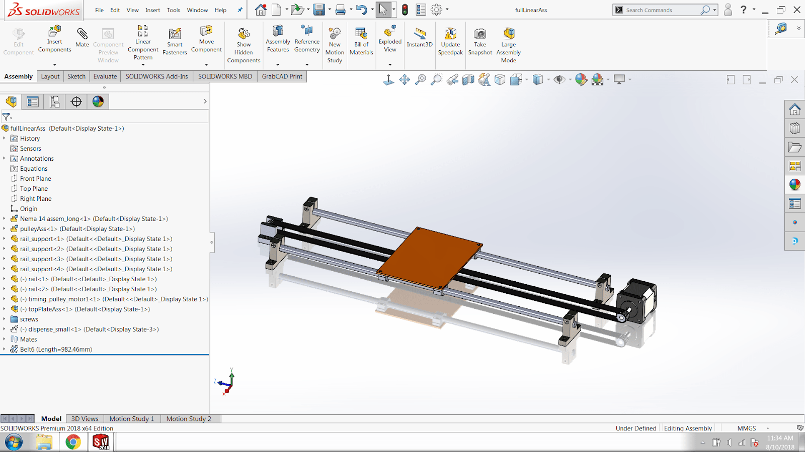
To run the track, there will be a stepper motor (which utilizes electrical pulses to rotate in very precise increments) connected to the top plate via a timing belt, with a timing pulley at the end opposite to the stepper motor. The motor can then be programmed to move the plate an exact distance and stop under the dispenser. My final design for the linear track in SOLIDWORKS has 46 components and is currently mated so that the track moves freely back and forth. (In my next blog, I will discuss how to animate this design with a path mate, a motor, and sensors to create the motion we want.) Below is the final SOLIDWORKS design of the linear track.
Layout
The next step in my design process is to essentially build around the linear track of the base – I started with a floor base. Right away I knew that the size of my machine probably wouldn’t be perfect on the first attempt. To combat this, it was essential to make meaningful sketches and features that wouldn’t break if I had to update them. Everything must be fully constrained and purposefully make use of this origin. I also thought this would help create a series of dimensions driven by equations so that if I were to change the width I could change a straightforward equation which would help me stay consistent throughout the body components like the walls, floor, back, and top plates.
My original SOLIDWORKS design was a standard rectangle enclosure, but that’s no fun so instead, I created a mostly open frame with some curvature in the front. Let’s take a look at the final design of one of the walls and break it down.
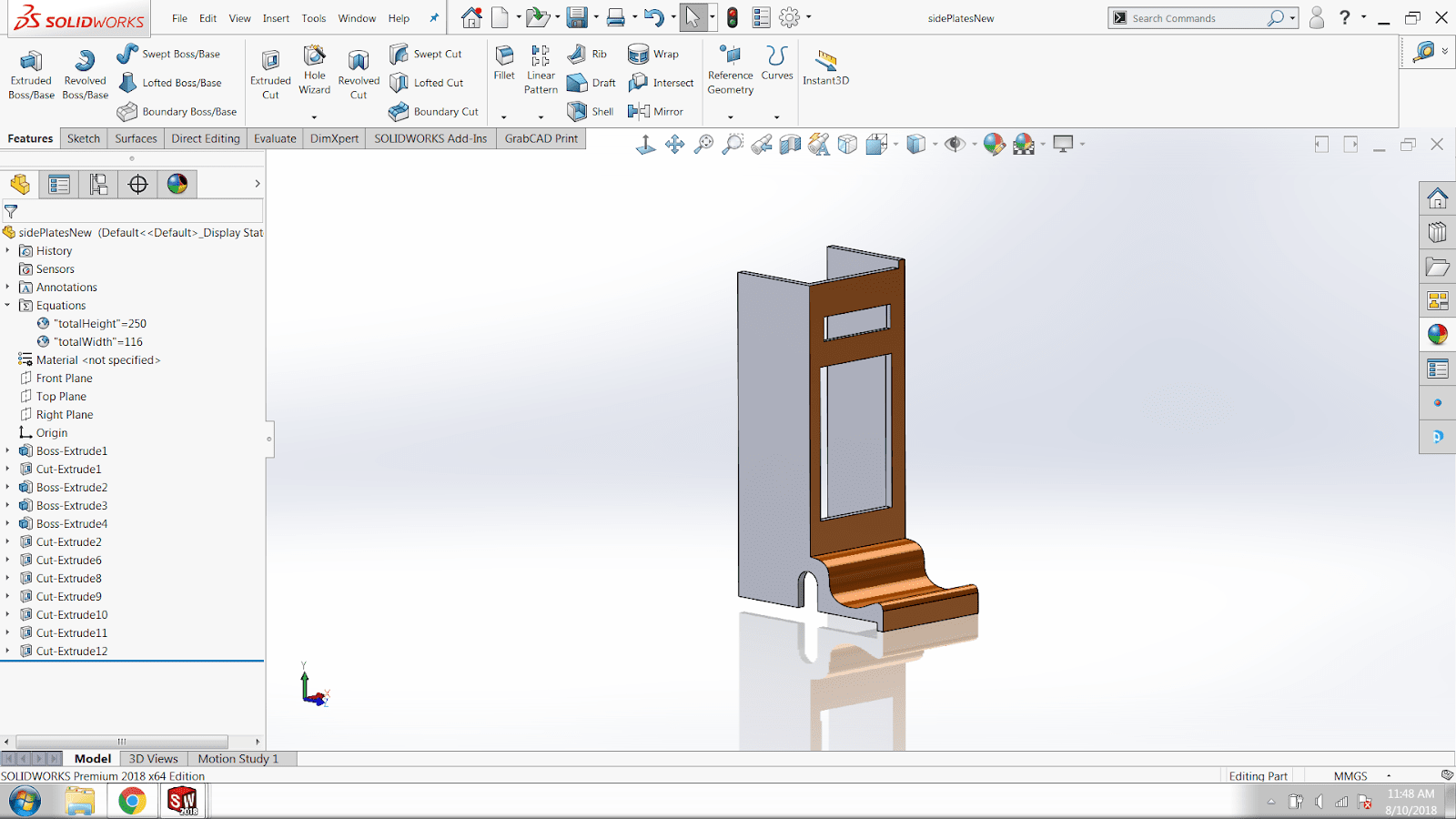
In the image above you can see the side plate that houses the LCD screen and coin acceptor. There are some cutouts for those components as well as a cutout so that the timing belt can be fed through and connect to the stepper motor which is secured underneath. The front curvature is created with a spline and a cut to create some dimension. The piece itself is thin and hollow to conserve material and weight. There are small cuts that allow the pieces to fit together to be flush and secure.
After creating the side plate, I did a little research on what kind of coin acceptor I wanted. Once I found one that I liked, I realized that I undershot the dimensions of the base size. So I reworked the model so it could adequately hold the coin acceptor, then went through and changed the equations of the other pieces to match.
Reservoir Design
Once the base was complete, I created the drink holder which screws into different sized bottles and holds them upside down. Once the valve is pushed up from the bottom, it dispenses a set of 30mL amount correctly then refills once the pressure is relieved. This design uses gravity rather than a pump which is the best fit for the design. See one of the holders in the image below.
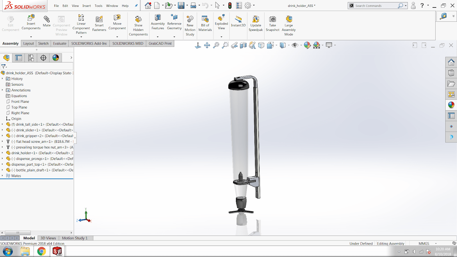
During the design process, I was able to use surfacing techniques to create organic shapes. Surfacing is used for building the top planes or surfaces of a part and then knitting them together and thickening them to form a solid body. I haven’t had a lot of experience using these techniques but they can create beautiful flowing parts.
I used surfacing to build the top suction cup holder which is connected by a spring so it can extend a few inches up and is held securely down by the spring mechanism. Once I created one drink mechanism, I moved on to the entire drink section which can house four different drinks up to 800 mL and from end-to-end is about a foot in length.
At first, I didn’t make the body components large enough to house the size of the dispenser so I went through again and changed the equations. (Another instance where I’m glad I thought through my design intent in the beginning).
So now I have completed the linear track with a motor and pulley, the body, the drink dispensers, coin acceptor, and LCD screen. The last component I need to create in SOLIDWORKS is the mechanism to push up against the dispenser.
Designing the Dispensing Mechanism
For this SOLIDWORKS design, I knew I needed something to rest on my linear track and to extend and retract vertically. I looked into a linear actuator system, but that didn’t suit my needs. Then I decided to try to use a stepper motor again to create a perfect extend amount. The consistent stepper motor would make coding easier plus they were inexpensive – perfect! The only problem now is how to convert the rotary motion into linear. I decided to go with a rack and pinon solution which can be found in the steering of a car.
I created the rack and the pinion by using the SOLIDWORKS design library. I made the spur gear and rack to my exact configuration. All I had to do was choose the module, the number of teeth, shaft diameter, pitch angle, etc. and the perfect spur gear was created. I then made the rack in the same way.
Then, using SOLIDWORKS mechanical mates I made a rack and pinion mate of the two components as well as a distance mate to make sure the teeth aligned. Now my stepper motor could move linearly and push the dispenser. I initially used the same Nema 17 motor as I did on the linear track, but I found it was a bit too large.
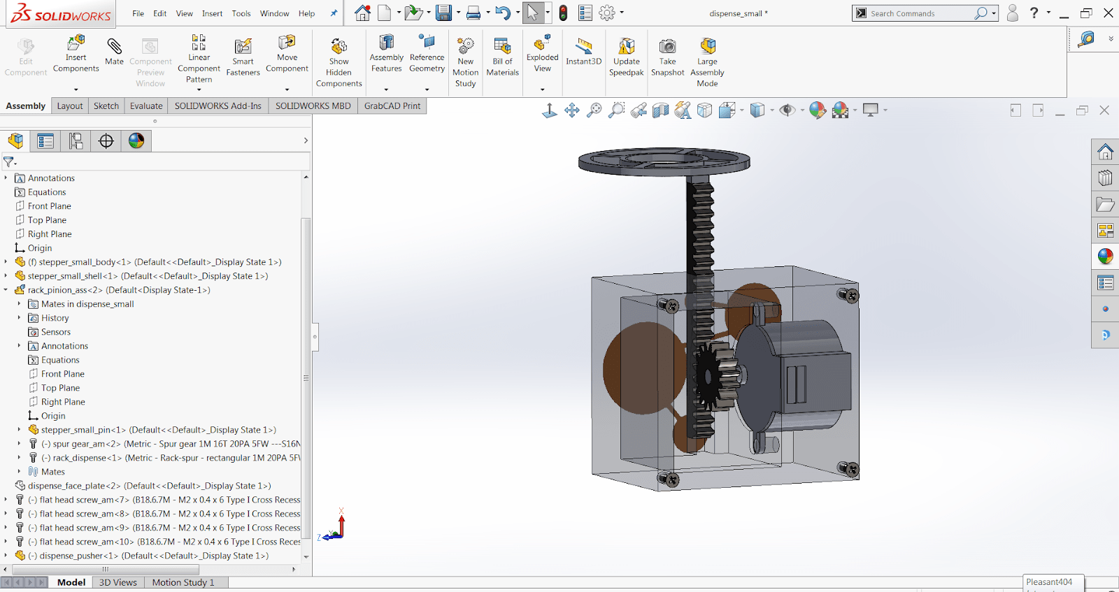
I was able to find a smaller option that is circular with the mounts in the opposite direction as I wanted the gear, so I decided to make a casing to hold it in places. The stepper motor, housing, rack and pinion, and the dispenser pushing plate can be seen the photo below (the casing is transparent and the back plate is taken off to allow for a better view).
Once the final mechanism is in place, the machine is complete; 111 components in total. It took a little less than two weeks from the original idea to a complete design. With SOLIDWORKS, I know that my sizing is correct which will save prototyping time; I can send the SOLIDWORKS part files almost directly to a 3D printer.
Next week I will cover motion and animation including some tutorials on how to set up your own motion study. I will also cover using Interference Detection to verify parts fit properly. In my third blog, I will start the prints and discuss the coding behind the final project, which will use an Arduino.
If you need help bringing your ideas to life let us know! Don’t forget to check back or subscribe for the next parts of the blog series and the grand product reveal.

Related Articles
Optimize Your Designs While Cutting Costs with SOLIDWORKS Simulation Tools
How to Get a SOLIDWORKS Free Trial
Women in Engineering: Taking a Step to Bridge the Gap
3D Printing Company Finds their Way to ABCs Shark Tank
About the Author
 Madison Bryce is a sophomore at the University of Michigan. She is studying Mechanical Engineering with a minor in Computer Science. Madison has four years of CAD experience and joined the Fisher Unitech team to share and grow this knowledge. Madison is a Certified SOLIDWORKS Associate (CSWA), Certified SOLIDWORKS Professional (CSWP), and a Certified DriveWorksXpress Associate. Madison’s dream is to one day become a roller coaster engineer. She is currently in a theme park engineering group at the University of Michigan.