SOLIDWORKS 2018 Improves Productivity with Mesh, Tab & Slot, and Sketch Features
 A decrease in productivity can create a landslide of side effects amongst your engineering and design teams, and ultimately impact time to market. That’s why SOLIDWORKS 2018 made improvements and offered new features to keep your design process flowing smoothly.
In our What’s New in SOLIDWORKS 2018 blog series we’ve been taking a look at new features and enhancements across the entire SOLIDWORKS 2018 portfolio. In this blog, we’ll be looking at improvements in productivity within SOLIDWORKS Mesh and Sketch capabilities, and a new assembly tool called Tab and Slot. Let’s take a look.
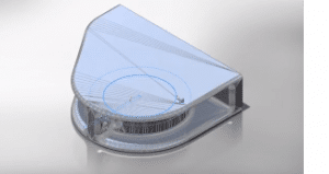
SOLIDWORKS 2018 Mesh Data
SOLIDWORKS 2018 introduces new ways you can utilize mesh data offering more possibilities than ever before for a variety of formats including stl., obj., and additive manufacturing files.
First off, graphical mesh geometry now supports material textures and real view appearances. Likewise, you can now perform sections on graphical mesh data as well. As a result, you can now better visualize and fully understand your mesh geometry right inside of SOLIDWORKS.
However, we can do much more with mesh geometry starting with the new surface from mesh feature a tool that enables you to turn mesh data into SOLIDWORKS surfaces quickly, utilizing a simple workflow. Just choose the type of surface you wish to create, then using the purpose-built Paint Select Facets tool you can easily swipe to select a handful of faces for the desired surface.
Within your design, not every surface needs to be selected. By simply choosing calculate, SOLIDWORKS will automatically gather the remaining faces for you and create the appropriate surface. Once any number of surfaces have been created in this manner, they’ll benefit from all the surfacing capabilities found in SOLIDWORKS allowing you to take full advantage of those familiar tools.
New Mesh body type
SOLIDWORKS 2018 also introduces the new mesh body type. Any graphical mesh can be converted into a mesh body quickly from the right mouse menu. Mesh bodies are similar to solid bodies in that they are watertight, have mass properties associated with them, and can be sectioned normally. But they do have some differences which we’ll talk about in a moment.
New workflows specific to mesh geometry
You can take your mesh data much further with some powerful new workflows specific to mesh geometry. For instance, you can add geometry to mesh files using all the familiar tools you’re used to in SOLIDWORKS. You can even reference the underlying mesh geometry when adding sketch relationships. The only difference, however is that these features aren’t automatically merged with the mesh geometry. To do that, you can now also convert traditional style bodies into mesh bodies as well graphical mesh as I mentioned above. This ultimately allows you to take any geometry you’ve created and perform a variety of Boolean style features to further manipulate your mesh geometry. A full list of these features can be seen in the video below.
Finally, like any other SOLIDWORKS file, these can be inserted into your assemblies and mated into position like any other component. This means you can now directly use your mesh data within all your SOLIDWORKS designs.

New Tab and Slot feature
A costly part of the manufacturing process is creating fixtures. So many designers are now turning to self-fixturing design techniques to reduce assembly and setup costs in the manufacturing process. SOLIDWORKS 2018 introduces a powerful tab and slot tool to automate this design step. Tab and slot can be created on parts in an assembly, a single part, or a multi-body part.
You start by choosing an edge to define the tab and a face to define where the slot will terminate. Offsets can be applied to control the tab distance from the ends. Spacing can be defined equally among a given number of instances or by defined length. The length of each tab can easily be specified and height can be a blind value or up to or offset from the selected surface.
Corner treatments such as fillets and chamfers can be applied to the tabs, and their size can be specified. The clearance between the slot and tab can be defined as well and, SOLIDWORKS creates features in both components to meet these specifications.
The new tab and slot feature not only reduces design time by automating the creation of these features but reduces manufacturing costs by minimizing the need to build expensive fixtures that can delay manufacturing.
Improved Sketching capabilities
There are some great new capabilities that enhance existing sketch workflows. SOLIDWORKS 2018 gives users more flexibility when working with arcs and splines. Users can now switch the tangency direction using the new option on the right mouse button menu. This new option eliminates the need to delete and recreate entities, which could otherwise cause a downstream failure of reference features.
Now when working with 3D sketches, users can build in symmetry at any time by mirroring sketch entities. Not only that, planes can also be used as a mirror reference in both 2D and 3D sketches. Symmetric relations are captured and maintained giving you a visualization of the complete shape as you refine your design. Now you can build in all the design intent you need right from the start.
We hope you enjoyed this inside look at SOLIDWORKS 2018 mesh, tab and slot, and sketch enhancements. To see more of what’s new in SOLIDWORKS 2018 check out the related articles below.
What’s New in SOLIDWORKS 2018 Blog Series
SOLIDWORKS 2018 3D File Support
SOLIDWORKS 2018 User Experience
About the Author
 Angelle Erickson writes about how companies are using innovative technologies, such as 3D printers and SOLIDWORKS software to increase productivity, improve product development processes, and maximize business potential.