Comparing SOLIDWORKS Motion Analysis and SOLIDWORKS Mate Controller
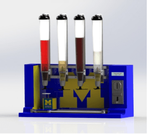 Welcome back to my blog series where I’m taking you on the journey from an idea to a working model. See how I took my concept of an automated drink dispenser, designed it, 3D modeled it, coded it, and eventually, 3D printed it. In my previous blog, I discussed the design process using SOLIDWORKS 3D CAD software. In today’s continuation, I show how I automated my machine directly in SOLIDWORKS and discuss some of the methods I used for coding the machine (including SOLIDWORKS motion analysis and mate controller) to match the automation I modeled. In future posts, I will show the process of 3D printing my drink dispenser using a Stratasys 3D Printer.
There are several ways to simulate motion in SOLIDWORKS – structural simulation, plastic simulation, and flow simulation to name a few – I could use these methods to test the strength of my machine, to see if the liquids would correctly flow, etc. These simulations can be useful in their ways, but the movement I’m concerned about is that of which I will be programming, namely the linear motion of the track as well as the functions of the dispensing mechanism. To show this motion, I tried two methods, mate controller, and motion analysis, and found that one was more efficient for the needs of my model.
SOLIDWORKS Motion Analysis
Motion studies in SOLIDWORKS run the gamut, from animation to basic motions, to the motion analysis add-in available with SOLIDWORKS premium. As you advance from animation to motion analysis, more laws of physics will apply to make the study more realistic. Animation is used to animate the motion of assemblies, such as adding a motor. Basic Motion is used to approximate the effects of motors, springs, contact, and gravity on assemblies.
Motion Analysis is for accurately simulating and analyzing the impact of motion elements such as forces, springs, dampers, and friction. Motion Analysis uses computationally robust kinematic solvers and accounts for material properties as well as mass and inertia in the computations.
I decided to try Motion Analysis due to its vast amount of options and availability. I added motors to the different components of the liner track and I could choose whether or not to create a constant speed, distance, oscillating, segments, etc. The original set up is a time-based motion study meaning that motors, forces, and gravity (among others) would be applied after a given time.
After a little research, I found it was possible to set up an event-based study. In an event-based study, you can control when a force is applied based on whether there is a trigger, such as a task was previously begun or ended. Event-based motion is beneficial because you can use all types of triggers to initiate an action rather than relying on time alone. For example, imagine you were building a Rube Goldberg machine. It would be hard to calculate the exact time, say the third component of the device, is set off but you could use the end of the second task quite effectively. In motion analysis, it is possible to incorporate a contact point in the study or make use of a sensor to add to the realism and to create animation easier.
While motion analysis contains powerful tools that would allow me to create sensors to trigger events correctly, I only want to simulate the motion of the track and dispensing mechanism.
While the effects of gravity, friction, and forces are all interesting, they are not exactly relevant to the animation I wish to create. I have no springs, dampeners, and friction is nearly negligible due to the linear rails and bearings. I found that all I wanted to control was the stepper motor connected to the belt and the stepper motor connected to the rack. I created these components and built my final animation.
Although this method was valid and could control the motors and contact accordingly, it took time to understand the different components of a motion study and how to integrate them all correctly. Since I’m only worried about the end animation, I decided to look for a fast and easy to manipulate method.
SOLIDWORKS Mate Controller
The concept of the Mate Controller is that after mates define an assembly, you can take the numerical mates, rather than those based on planes or features, and control those numbers. A typical use for this method is to create fluid movements for something that needs to move to different positions.
Take for example a robotic arm of an excavator, the construction truck that digs. There may be a position where the truck arm begins, and then there may be a spot where it must go lower to dig, then another to scoop the dirt, etc. If there is an actuator on the arm to control how high above the earth the arm is, this actuator’s mate could be a distance or even an angle mate. If you use a mate controller to define the positions, you can create an animation that takes the arm and moves it from the beginning position to the end. You can control multiple mates at a time as well as having different positions to create all types of movements.
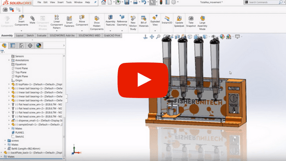
The Mate Controller is a simple solution to generate animation in my linear rail system. All I need to know is the distance to move and, based on my design, there is a specific amount the track must travel to be underneath the drink. I will use the Mate Controller to control the movements of a linear system. To learn how to configure the mate controller, watch my video of me setting up the animation.
Creating the final animation is like creating the blueprint for the code I need to write to control the machine in real life. I’m programming my machine using the hardware and software for Arduino, and I’m using the Arduino Uno board. My plan is to use two different stepper motors, a Nema 17 bipolar motor for the track and a ULN2003 5V Stepper Motor for the track and pinion set. I also have a different driver board for each to connect it to the Arduino. The driver boards will help with the overall programming, damage, and heat control due to the heatsinks they both house. I’m using 6-coin coin acceptor and a 16 x 2 LCD screen.
The Arduino contains both a library for stepper motors as well as LCD screens. The Arduino compiler/IDE accepts both C and C++ and when using an Arduino, you program a sketch then upload it to your board. When you first open a sketch you are given the following code:
void setup() {
// put your setup code here, to run once:
}
void loop() {
// put your main code here, to run repeatedly:
}
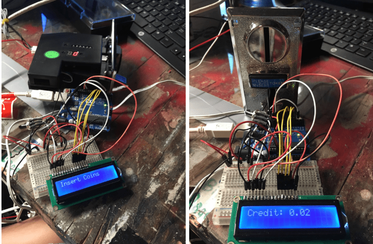
At this time, some of my code is still in progress, but I have completed the coin acceptor and the LCD screens. The machine initially displays “Please Insert Coins” and then once a customer inserts a coin, the screen changes to display “Credit:” and what the credit is. I also added a couple lines of code that turns the whole machine free for one drink if a particular free drink coin is inserted.
Below you can see a few images of my wiring to the board as well as how the display looks after inserting 2 pennies.
There is still quite a bit of code to complete, but working on the stepper motors haven’t been too complicated thanks to the built-in library and starter code Arduino provides. I also plan on adding LEDs either in strips lighting up the entire machine or to light up the drinks themselves.
In my next blog, I’m printing some components, finishing the code, and starting the final assembly – stay tuned!
Related Articles
SOLIDWORKS Designs: Fully Functional Drink Dispenser
Optimize Your Designs While Cutting Costs with SOLIDWORKS Simulation Tools
How to Get a SOLIDWORKS Free Trial
About the Author
 Madison Bryce is a sophomore at the University of Michigan. She is studying Mechanical Engineering with a minor in Computer Science. Madison has four years of CAD experience and joined the Fisher Unitech team to share and grow this knowledge. Madison is a Certified SOLIDWORKS Associate (CSWA), Certified SOLIDWORKS Professional (CSWP), and a Certified DriveWorksXpress Associate. Madison’s dream is to one day become a roller coaster engineer. She is currently in a theme park engineering group at the University of Michigan.