Save Time with SOLIDWORKS Simulation Feature: Blended Curvature-Based Mesh
Finite element modeling (FEM) continues to evolve and makes solving multiphysics problems easier and easier for users. No longer, are the days of dedicated engineers or programmers sitting in cubicles writing code to solve finite element problems. SOLIDWORKS Simulation has set the bar for making FEM easier for users while still being computationally powerful. In this blog, I will cover one of the newer capabilities in SOLIDWORKS Simulation that can save you a lot of time: the “Blended curvature-based mesh” feature.
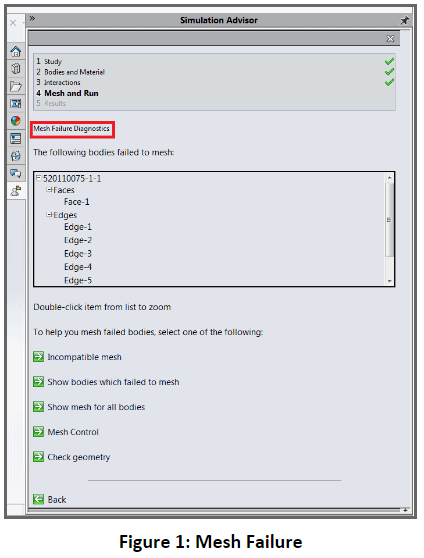
Ultimately, one of the hardest parts of modeling within the finite element realm is meshing. Often times meshing can be one of the most tedious and time-consuming aspects of setting up an FEA model prior to running. What happens if you get into the situation where there is a meshing failure as shown in Figure 1 below?
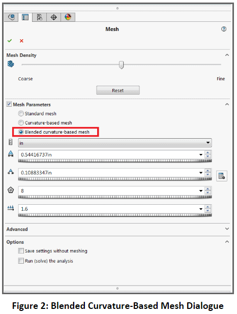
There are some great traditional approaches that I encourage you to use, such as mesh controls and incompatible meshing during mesh failures. However, in certain circumstances, even the combination of mesh controls and incompatible meshing may not resolve your meshing error. So what do you do? You use the SOLIDWORKS Simulation “Blended curvature-based mesh” feature as shown in Figure 2.
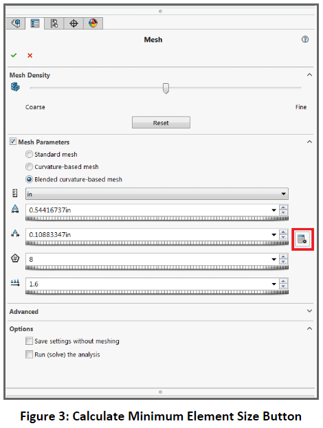
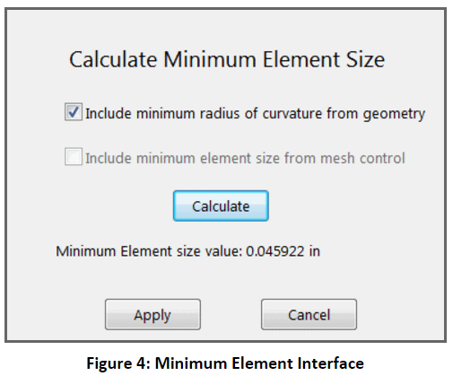
Upon setting up the minimum element size and sizing your mesh appropriately, you can create the blended curvature mesh and then run the analysis. In most scenarios, you will see that the blended curvature mesh will resolve meshing failures, and as a result, it is a very powerful tool to utilize. With that being said, there are some caveats to using a blended curvature-based mesh. With a blended curvature-based mesh you cannot utilize adaptive meshing, so all mesh refinement will have to be done manually. It should also be noted that in a lot of cases the mesher may take longer to mesh a model than the traditional mesher because it is a more sophisticated algorithm. Despite these small caveats, the blended curvature-based mesher is a valuable new feature of SOLIDWORKS Simulation, which will save you a lot of time when you run into complicated meshing scenarios. Until next time, best modeling!
Related Articles
- – Simulation Standard: The Right Tool for the Job
- – The Right Tool for the Job Part 2: The Single Body Limitation in SIM Xpress
- – The Right Tool for the Job Part 3: Getting your Fix with Fixtures