A Sensible CAD Workflow
I Convinced my Boss to let me Build America’s Favorite Yard Game
Whether you call it cornhole or bean bag toss, bags or sack toss, we can all agree on one thing: the game where you throw bean-filled pouches at a hole on a board has Americans interacting with family members and avoiding political arguments since 1974!
Here, in Minnesota, we affectionately call this game, “bags”. I’ll refer to it as such from now on. I’m not here to talk about how to play bags, but you can find rules here. We’re here to talk about how SOLIDWORKS design, costing, and rendering tools helped my stakeholders – in this case, my boss – approve decisions faster.
The Pitch
Our local office – located in beautiful Eden Prairie, MN – needed an entertaining space. The office is paired next to vacant patio that overlooks Lake Smetana to the east, and 494 to the south. What better way to spend an afternoon in June throwing bags with my colleagues? How can I make these to align with our corporate branding? The obvious answer was to make it myself. But I needed two things: a buy-in, and a budget.
Fortunately, SOLIDWORKS does both – easily.
The Design
Probably one of the easiest projects I’ve ever taken on is designing a bags platform. Let’s look at the official requirements for it:
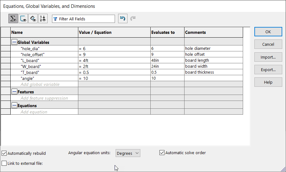
- Hole diameter is 6”.
- Hole is centered, 9” from top.
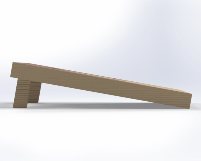
- Board is 4’x2’x1/2”.
- Board angle is approximately 10-degrees.
One workflow I’ve been enjoying storing these parameters as global variables under Tools> Equations. This way, I can call out any of the unique measurements to the design. It also makes it easier to link values on the fly by building equations.
The design will be made up of weldments and sheet metal. This allows me to get the nominal dimensions for the framing, legs, and board. My custom weldment profiles included several standard sizes of lumber members. To learn how to customize weldment profiles, visit here. My cut list is more descriptive than a standard BOM because it features the cut lengths of members. This can also be used to extract part costs using SOLIDWORKS Costing. We’ll get to that later.
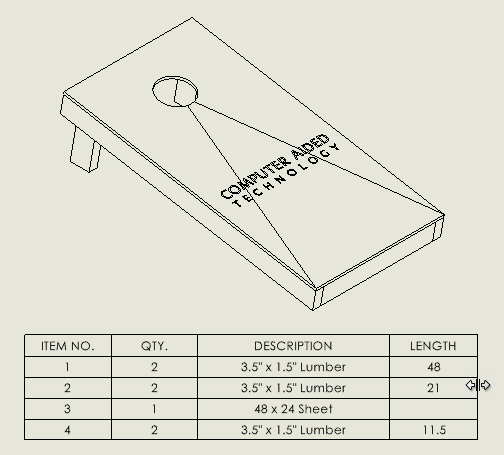
The “sheet metal” component cut list property description has been modified to include the bounding box length and width.
The Buy-in
It’s time to take the design a bit further. If my boss has any chance of approving this, I will need great visual supports. Insert: Visualize.
SOLIDWORKS Visualize helps create hyper-realistic product renderings using the same CAD SLDPRT and SLDASM files. It’s more robust than other rendering options in SOLIDWORKS like Photoview 360. It’s also not the easiest to learn. Therefore, adding appearances directly within SOLIDWORKS can save time.
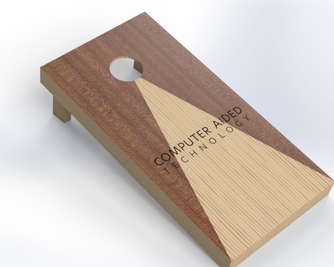
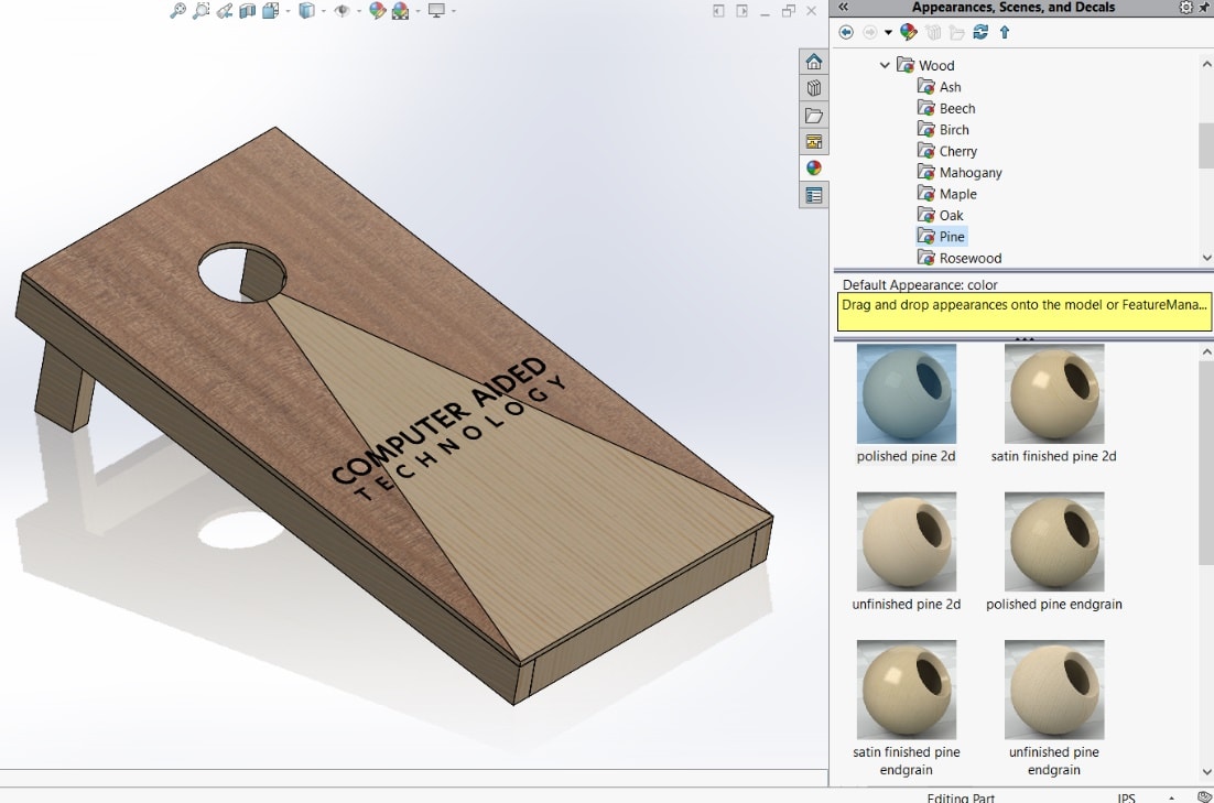
The appearances tab applies 2D cosmetic textures to faces, features, bodies, or parts. We can apply these and import this model directly into Visualize.
The first pass seems good at first, but a closer inspection shows that some of the model face patterns are going in the wrong direction.
This just won’t do. How will my boss be wooed into agreeing for an office “bags” set? Luckily, SOLIDWORKS appearances can address this issue quickly.
I can fix some of these faces by accessing some basic appearance controls in the PropertyManager,. First, I’ll RMB (right-click) the face where the pattern isn’t matched.
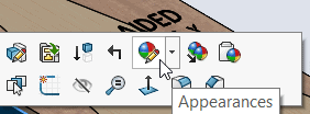
I will select my “face” filter on the mispositioned face. It may be necessary to re-apply the wood appearance.
Let’s point out a few things in the Appearances PropertyManager. The first, labelled “1”, is the “tack”. This will allow you to continuously apply appearances without having to RMB again. The “Mapping” tab allows users to control the mapping style, direction, and scale of the appearance. The “Axis Direction” allows you to change the angular reference direction. Lastly, rotation is what allows you to re-position the texture.
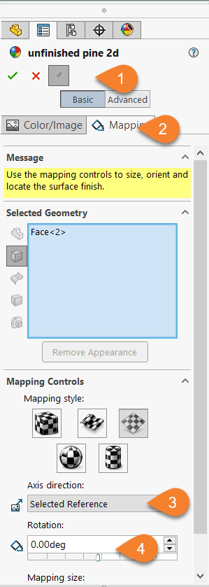
Make sure to select all the faces that you expect to have the same grain direction before applying the mapping controls. For more information, visit this SOLIDWORKS help page.
The rotation can be manually defined with number keys, left-clicked on for 45-degree incrementation, or click-dragged for 1-degree incrementation. Since the board angle must be 10-degrees for the regulation-size bags board, I’ll type in 10 degrees. I may have to use 170-degrees to get pattern rotation in the other direction.
I’ll continue this process until I have the expected grain directions.
Launching Visualize
Visualize Standard is free for members with active subscriptions with SOLIDWORKS Professional or Premium. To learn more about the benefits of Active Subscription, click here.
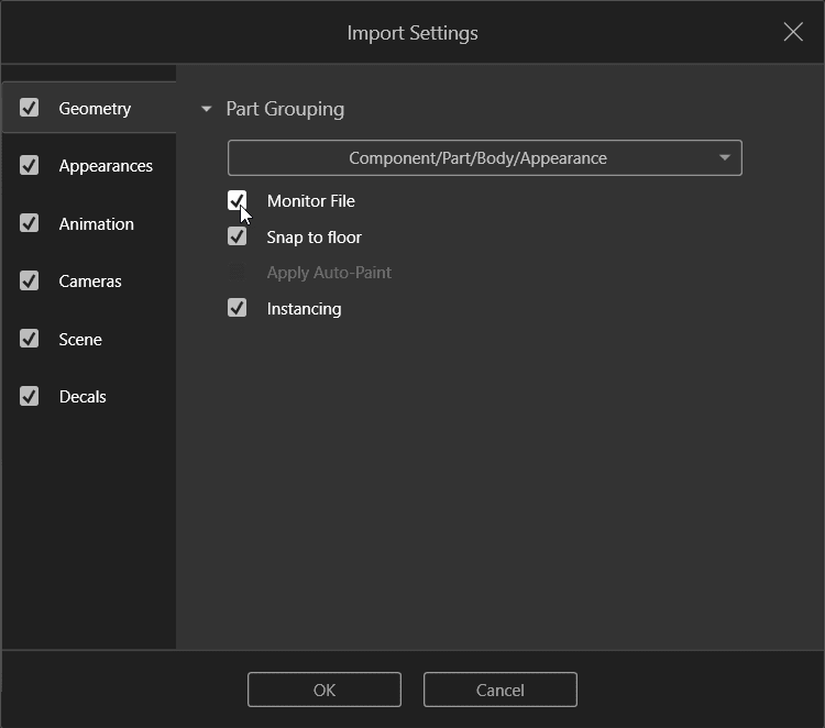
There are a few settings to know when importing your Visualize project. The first is the Part Grouping. Since this model is built through multi-body design with weldments and sheet metal, I’ll enable component/part/body/appearance as the part grouping. This allows me to apply a unique appearance to each body.
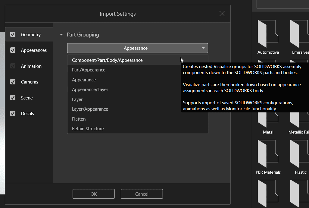
I’ll also make sure to enable “Monitor File”. This ensures the Visualize model will update according to any changes saved in the SOLIDWORKS model. If I forget to scale or rotate an appearance, I won’t need to use Visualize tools to modify it.
Once I re-mapped the bags board to the correct grain direction, I decided it still wasn’t enough. So, I modelled some bean bags and applied a burlap appearance. Of course, I colored them according to CATI colors. I also added the stone tiles that appear on our Eden Prairie office patio.
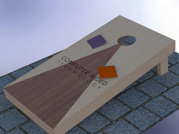
Wow, we now have an image that excites by showing the purpose of the board. This is just one of those powerful stories we can tell through Visualize. But, it’s just about to get a little more powerful…
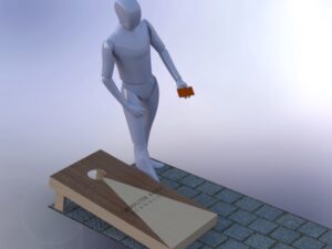
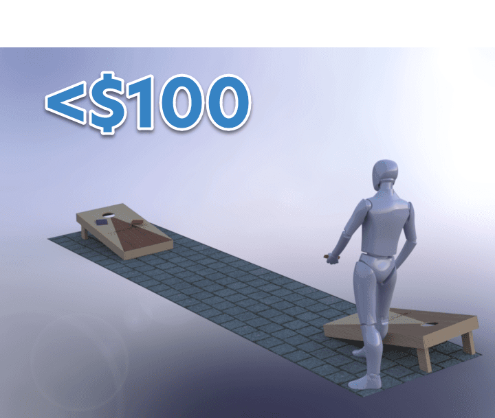
While the board toss image rendering was good, I really had to knock this out of the park. How would my boss be able to tell how much enjoyment and office comradery this would bring? The answer: Import human.
And since I didn’t have a CAD model of myself, I decided this articulated robot from GrabCAD might do.
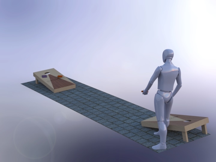

Oh, would you look at them having the time of their life? This clearly depicts the intended use of the product, which is what model rendering can illustrate. Now that’s a convincing sales pitch. Most of us might know already how to play this particular game, but could the same be said for your product? Does it communicate purpose in a professional manner?
And, is this enough to allow your stakeholders to buy-in? How do they know how much they need to buy-in? That leads us to the second necessity: the budget.
The Budget
All products need to fit within certain budget constraints. One incredibly helpful tool is SOLIDWORKS Costing. I’ve written a few blogs on the tool in the past: Costing template editor, Cost optimizing with Weldments I, Part II. It will help me get a total cost approximation for each board.
SOLIDWORKS Premium Costing allows assemblies to be evaluated. Assemblies include the option to price for purchased components like hardware.
A quick browse through the local lumber website can help get data to optimally build this.
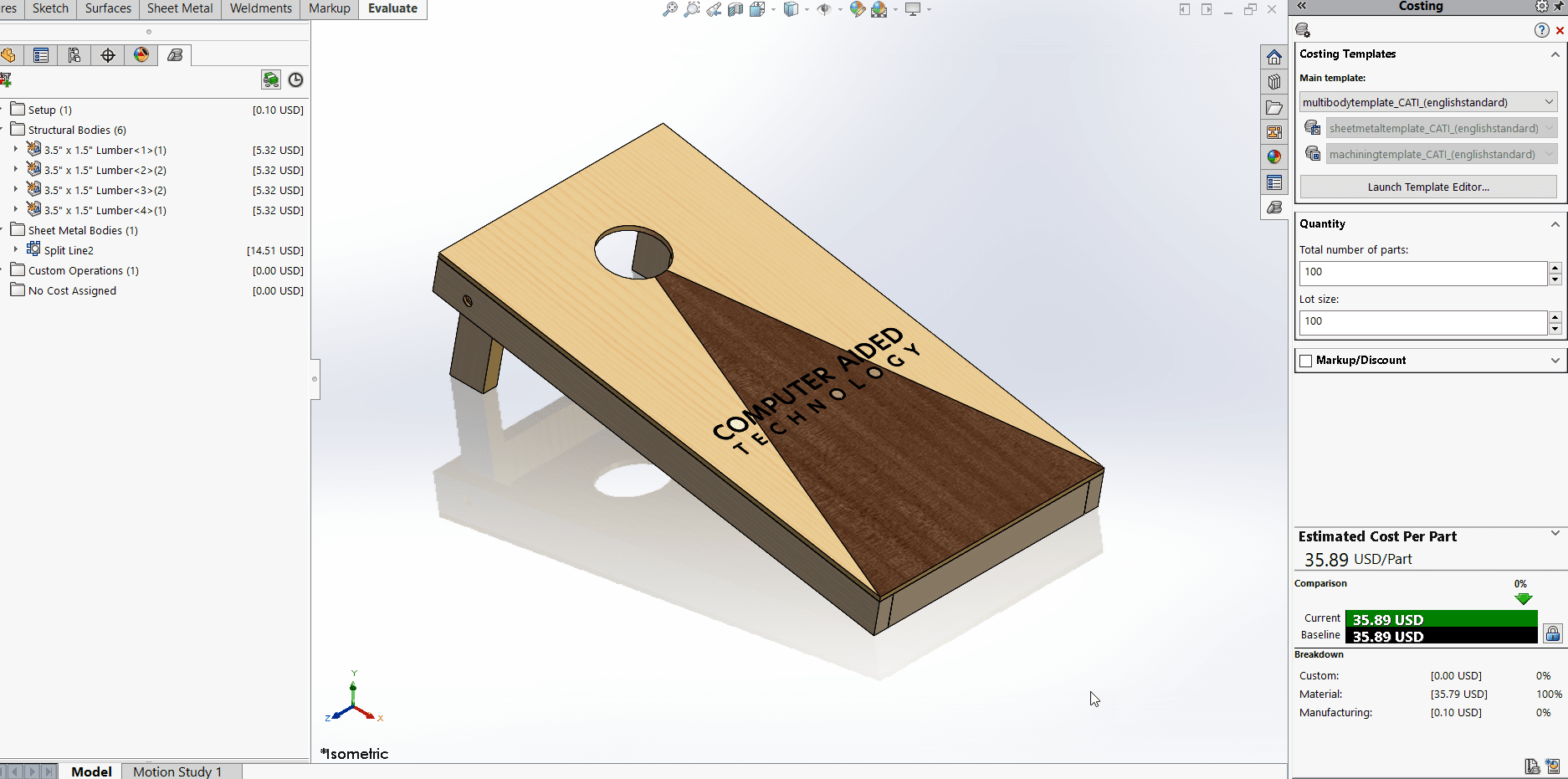
First, I’ll evaluate the cost of the part. This is an example of what SOLIDWORKS Professional can provide.
Now, let’s look at the cost of the overall assembly, which includes a secondary board, and purchased bean bags. This is meant for SOLIDWORKS Premium. I already own some extra hardware, so I’ve added the hardware to “No cost assigned”. Purchased parts can have custom property “price” added in the file properties.
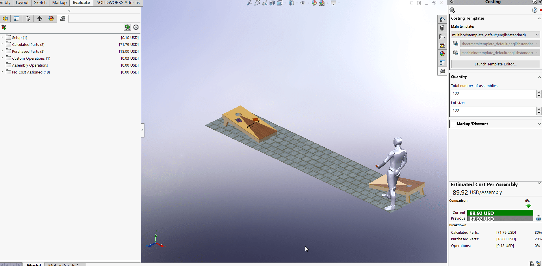
SOLIDWORKS Costing also tells me that it’s best to use 8ft members, instead of 12ft lumber, to be most cost-effective. This is the power of SOLIDWORKS Costing.
Results
Now, I can deliver both necessities for my proposal: the buy-in, and the budget. I’ve created both a visually appealing graphic with aesthetic design intent, and provided the overall cost of the product, within just two hours.
I can now go to my boss, propose the final design, and give him a budgetary estimate of under $100 to complete the project.
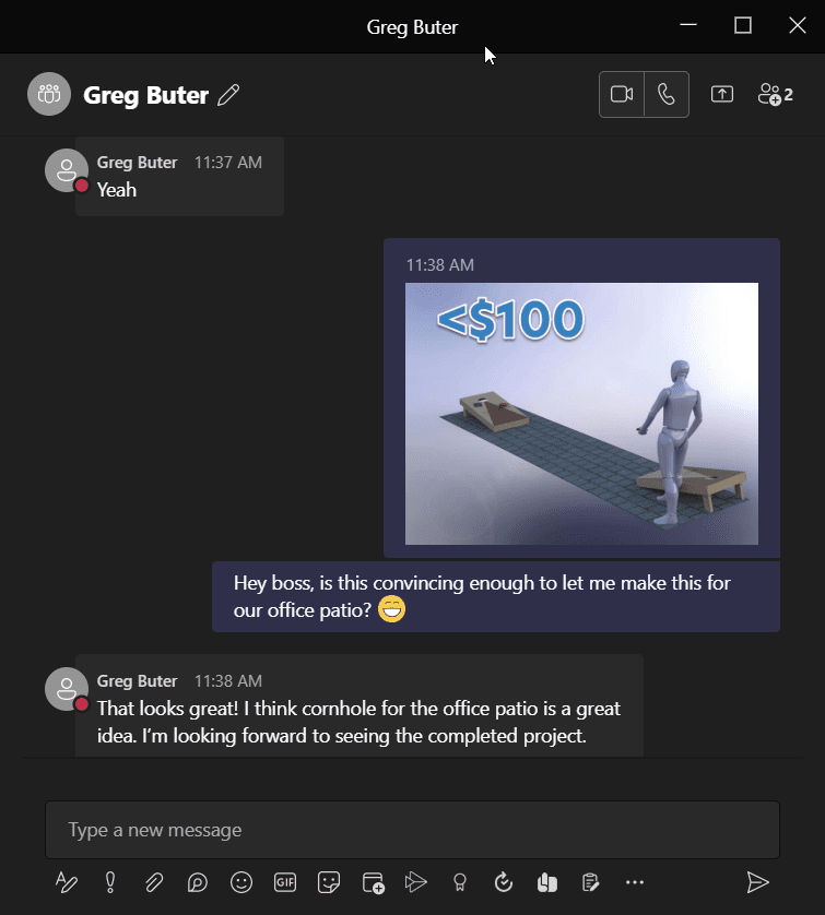
And that’s the story of how I convinced my boss to let me build America’s favorite game of — as he calls it– “Cornhole”.
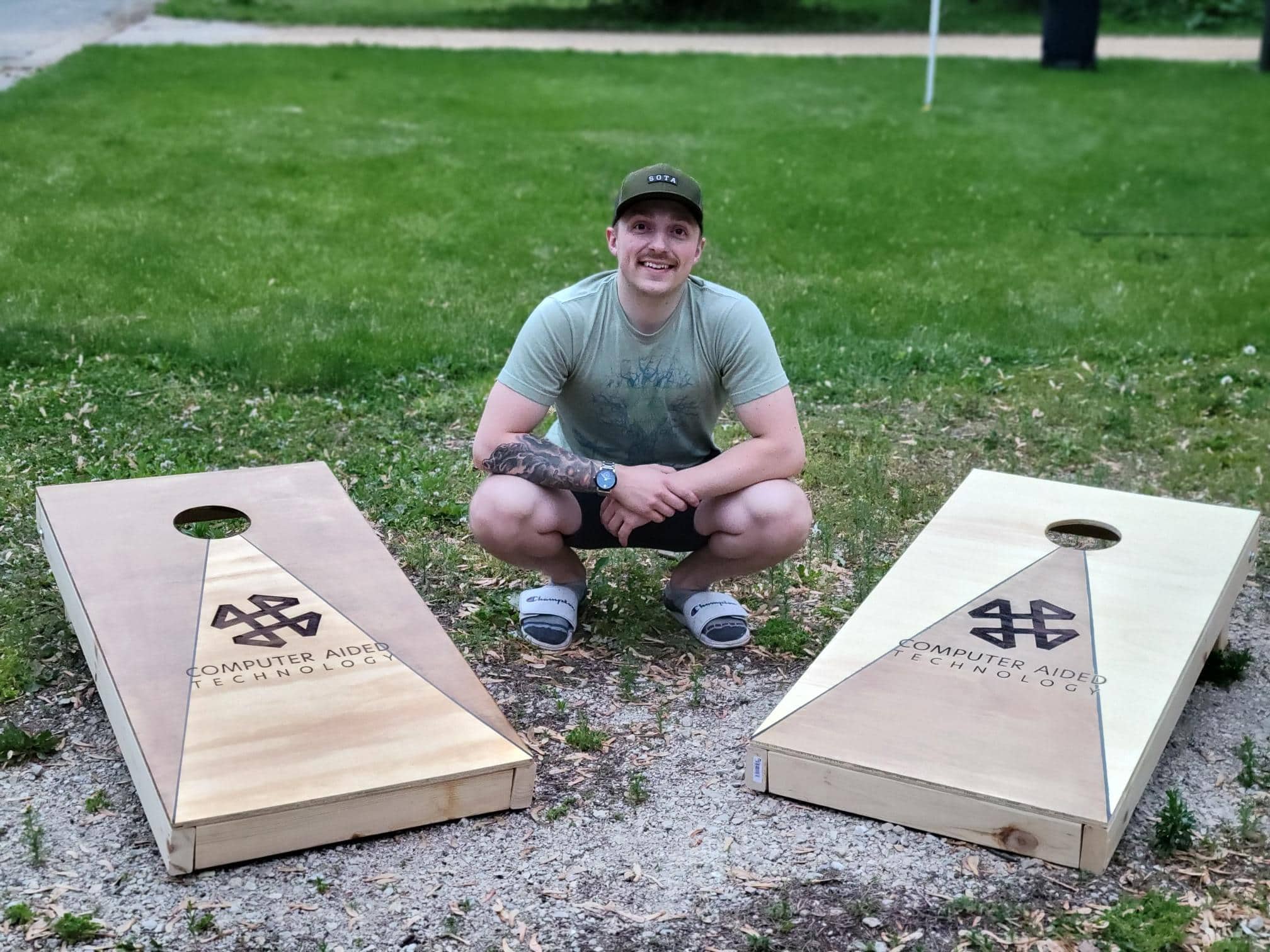
Here’s the finished product! A simple laser diode engraver did most of the heavy lifting. I also got to try out my new Milwaukee jigsaw, which was thoroughly enjoyable.
Conclusion
Whether you’re a highly valued startup that wants to render excitement and intrigue to your stakeholders, or whether you’re just trying to convince your wife to build that backyard hangout you’ve always wanted, Visualize brings to life what standard CAD modelling cannot. It’s included with active subscription for SOLIDWORKS Professional and Premium.
SOLIDWORKS Costing is included with SOLIDWORKS Professional (Premium for assemblies.) This tool will help you calculate in-house manufacturing costs for budget approval. It can also determine the “what if’s” of material procurement and manufacturing processes that optimize your lean product manufacturing. I used it to make sure I was wasting less, with 8ft instead of 12ft boards.
So, what are you waiting for? Get started by taking formal training through CATI, informal training through MySolidWorks, and start getting comfortable with the “yes” you’ll start receiving on your product development.
Best wishes and happy designing!
Jordan Kleinschmidt, CSWE
Application Engineer II
Computer Aided Technology